


8. Adjustment Procedure
8
−
14
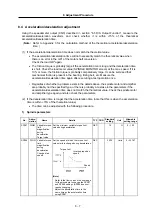
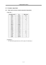
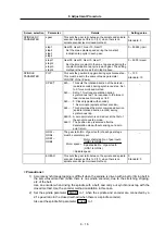
(3) The stop position deviates.
Cause Investigation
items Remedy Remarks
Machine factor
There is backlash,
slippage, etc., between
the spindle and encoder.
The stop position does not
deviate on the encoder axis.
•
The deceleration ratio
between the spindle and
encoder is not 1:1 or 1: 2.
Set the deceleration ratio
to 1:1 or 1:2.
The position shift changed to
2048 at a 1:2 deceleration
ratio between the spindle and
encoder. (Deviation on the
encoder axis.)
The position does not
change because the
spindle rotates once at
2048 in this case.
(However, the position
changes on the encoder
axis.)
Noise
There is a break in the
encoder cable.
Use one encoder cable.
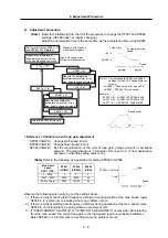
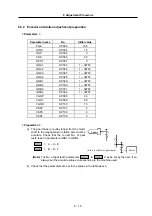
(4) The spindle vibrates when stopped.
Cause Investigation
items Remedy Remarks
The parameter
setting is incorrect.
The gear ratio parameters
GRA1 to 4 and GRB1 to 4 are
incorrect.
Correctly set the gear
ratio parameters.
Orientation
adjustment
The vibration frequency is
several Hz.
Lower the position loop
gain PGM and PGE .
The vibration frequency is
10Hz or more.
Lower the speed loop
gain VGOP and
VGOI during
orientation.
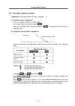
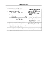
(5) An orientation completed signal is not output.
Cause Investigation
items Remedy Remarks
Refer to item (1) "Orientation is not carried out".
The machine load
is heavy
The in-position (parameter
OINP ) value is too small.
Reconsider the in-position
range.
(Parameter x OINP )
An orientation completed
signal is output by changing
the control during orientation
to PI control.
Reconsider the speed
loop gain during
orientation (parameters
VGOP and VGOI ).
This may also
apply if hunting
occurs at the
stop point.