


3 System Configuration
3.2 Applicable PLC
20
FX
3U
-1PG User's Manual
3.2
Applicable PLC
The version number can be checked by reading the last three digits of device D8001/D8101.
*1.
An FX
2NC
-CNV-IF or FX
3UC
-1PS-5V is necessary to connect the FX
3U
-1PG with the FX
3UC
PLC.
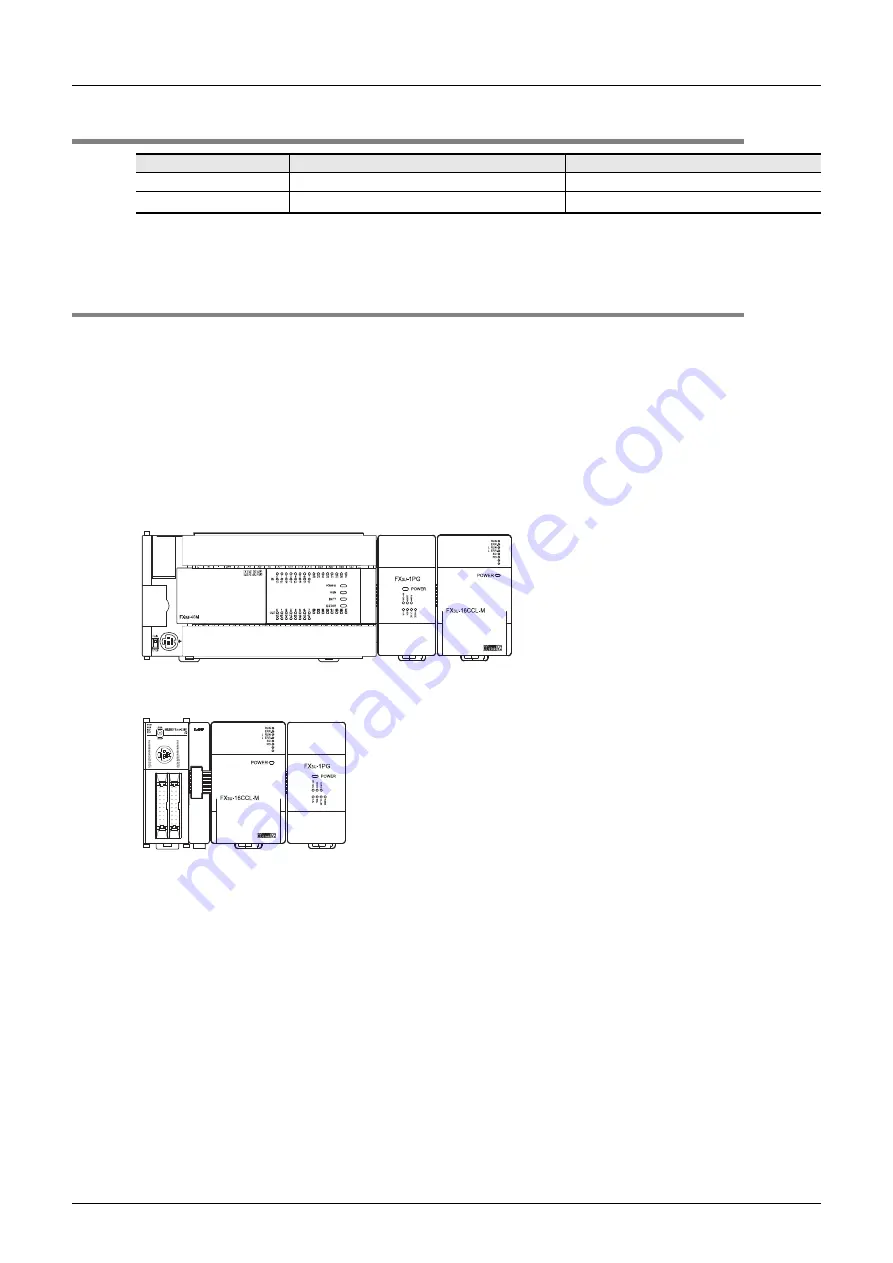
3.3
Connection with PLC
The FX
3U
-1PG connects to a PLC via an extension cable.
The FX
3U
-1PG is handled as a special extension block of the PLC. The unit number of the FX
3U
-1PG is
automatically assigned No. 0 to No. 7 (Unit No. 1 to No. 7 is assigned when the main unit is an FX
3UC
-32MT-
LT(-2).) starting from the special function unit/block closest to the PLC main unit.
(This unit number is used in FROM/TO instructions.)
For details on the assignment of the I/O number and unit number of the PLC, refer to the following manual
corresponding to the connected PLC.
→
Refer to FX
3U
Hardware Edition.
→
Refer to FX
3UC
Hardware Edition.
• An FX
2NC
-CNV-IF or FX
3UC
-1PS-5V is necessary to connect the FX
3U
-1PG to the FX
3UC
PLC.
• For extension, the separately available FX
0N
-65EC/FX
0N
-30EC extension cable and FX
2N
-CNV-BC are
used. One extension cable can be used per system.
• The number of I/O points occupied by the FX
3U
-1PG is eight. Make sure that the total number of I/O points
(occupied I/O points) of the main unit, extension unit(s), extension block(s) and the number of points
occupied by special function blocks does not exceed the maximum number of I/O points of the PLC.
For information on the maximum number of I/O points of the PLC, refer to the respective product manual.
→
Refer to FX
3U
Hardware Edition.
→
Refer to FX
3UC
Hardware Edition.
Model name
Applicability
Maximum number of connectable units
FX
3U
Series PLC
Ver. 2.20 and later
8 units
FX
3UC
Series PLC
*1
Ver. 2.20 and later
6 units
FX
3U
PLC
FX
3U
-1PG
FX
3UC
PLC
FX
3U
-1PG
FX
2NC
-CNV-IF
Other
extension
units/blocks
Other
extension
units/blocks
Содержание FX3U-1PG
Страница 1: ...FX3U 1PG USER S MANUAL ...
Страница 2: ......
Страница 6: ...Safety Precautions Read these precautions before use 4 MEMO ...
Страница 142: ...Appendix C Differences with FX2N 1PG Appendix C 3 Differences in Operation 136 FX3U 1PG User s Manual MEMO ...
Страница 145: ......


