


1
1 PRODUCT CHECKING AND PARTS IDENTIFICATION
Unpack the inverter and check the capacity plate on the front cover and the rating plate on the inverter side face to
ensure that the product agrees with your order and the inverter is intact.
REMARKS
For removal and reinstallation of covers, refer to
page 4
Operation panel (FR-DU07)
Front cover
EMC filter ON/OFF connector
Control circuit
terminal block
AU/PTC switchover switch
Main circuit
terminal block
Charge lamp
Lit when power
is supplied to
the main circuit
Power lamp
Lit when the control circuit
(R1/L11, S1/L21) is supplied
with power.
Cooling fan
PU connector
RS-485 terminals
Connector for plug-in option connection
(Refer to the instruction manual of options.)
Alarm lamp
Lit when the inverter is
in the alarm status
(major fault).
Capacity plate
Inverter type
Serial number
Capacity plate
Rating plate
Combed shaped wiring cover
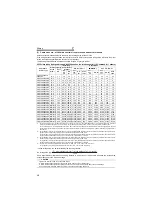
- EC
FR-F740-00126-EC
00126
Symbol
00023
to
12120
Displays the rated current
Type Number
FR -
-
F740
Symbol
F740
Voltage Class
Three-phase
400V class
Rating plate
Inverter type
Input rating
Output rating
Serial number
FR-F740-00126-EC
LD (50 C) XXA
SLD (40 C) XXA
Overload Current Rating Ambient Temperature
LD
120% 60s, 150% 3s
50 C
SLD
110% 60s, 120% 3s
40 C
•
Inverter Type
(Refer to page 22)
(Refer to page 22)
(Refer to the Instruction Manual (applied).)
(Refer to page 4)
(Refer to page 8)
(Refer to page 9)
(Refer to page 84)
(Refer to page 22)
(Refer to page 14)
(Refer to page 11)
•
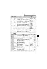
Accessory
· Fan cover fixing screws (00620 or less)
(Refer to page 134)
· DC reactor supplied (01800 or more)
Capacity
Screw Size (mm)
Number
00083, 00126
M3
×
35
1
00170 to 00380
M4
×
40
2
00470, 00620
M4
×
50
1
(Refer to page 9)
(Refer to page 4)
Содержание FR-F 700 EC
Страница 2: ......
Страница 142: ...MEMO ...


