


13
(2) Notes on earthing
• Leakage currents flow in the inverter. To prevent an electric shock, the inverter and motor must be earthed. This inverter
must be earthed. Earthing must conform to the requirements of national and local safety regulations and electrical
codes. (JIS, NEC section 250, IEC 536 class 1 and other applicable standards)
• Use the dedicated earth terminal to earth the inverter.
(Do not use the screw in the casing, chassis, etc.)
• Use the thickest possible earth cable. Use the cable whose size is equal to or greater than that indicated in the above
table, and minimize the cable length. The earthing point should be as near as possible to the inverter.
To be compliant with the European Directive (Low Voltage Directive), earth the inverter according to
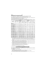
(3) Total wiring length
The overall wiring length for connection of a single motor or multiple motors should be within the value in the table below.
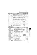
* For the 01800 or more, the setting range of
Pr. 72 PWM frequency selection
is "0 to 6".
When driving a 400V class motor by the inverter, surge voltages attributable to the wiring constants may occur at
the motor terminals, deteriorating the insulation of the motor.
Take the following measures in this case.
(1) Connect the surge voltage suppression filter (FR-ASF-H) to the 01160 or less and the sine wave filter (MT-BSL/
BSC) to the 01800 or more on the inverter output side.
(4) Cable size of the control circuit power supply (terminal R1/L11, S1/L21)
· Terminal Screw Size: M4
· Cable size: 0.75mm
2
to 2mm
2
· Tightening torque: 1.5N·m
Pr. 72 PWM frequency selection
Setting
(carrier frequency) *
00023
00038
00052 or
More
2 (2kH) or less
300m
500m
500m
3 (3kHz), 4 (4kHz)
200m
300m
500m
5 (5kHz) to 9 (9kHz)
100m
10 (10kHz) or more
50m
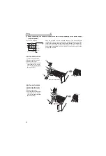
Total wiring length (00038 or more)
CAUTION
· Especially for long-distance wiring, the inverter may be affected by a charging current caused by the stray capacitances of the
wiring, leading to a malfunction of the overcurrent protective function or fast response current limit function or a malfunction or
fault of the equipment connected on the inverter output side. If fast-response current limit function malfunctions, disable this
function. (For
Pr.156 Stall prevention operation selection, refer to the Instruction Manual (applied).
)
· For details of
Pr. 72 PWM frequency selection , refer to the Instruction Manual (applied)
. When using an optional sine wave filter
(MT-BSL/BSC) for the 01800 or more, set “25” in
Pr.72
(2.5kHz).
For explanation of surge voltage suppression filter (FR-ASF-H) and sine wave filter (MT-BSL/BSC), refer to the manual of
each option.
500m or less
300m
300m
300m + 300m = 600m
Содержание FR-F 700 EC
Страница 2: ......
Страница 142: ...MEMO ...


