background image

S e r v i c e   I n f o r m a t i o n

OWNER’S HANDBOOK   4-39

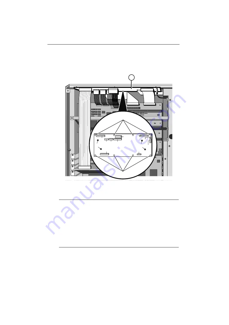
Motherboard Power Distribution Panel

The motherboard power distribution panelis fixed to the inner roof of the
electronics chamber and is positioned at right angles to the motherboard.
The following illustration shows the connectors and the eight securing
screws on the board:

2

2

8

9

10

11

7

12

6

5

4

3

1

13

13

Figure 4-38  Motherboard Power Distribution Panel

1.

Power Distribution Panel

8.

Front Panel Connector

2.

Securing Screws

9.

Loudspeaker Connector

3.

SMIC Card Connector

10.

Auxiliary Power Connector

4.

Power to Motherboard

11.

Fan Board Connector

5.

Power to Motherboard

12.

System Controller Connector

6.

Power to Motherboard

13.

Bus Bar Connections

7.

3.3 Volt Supply to
Motherboard

Removing

1. 

Unplug all connectors on the panel.

2. 

Detach the bus bars (two pairs) from the panel.

3. 

Remove eight securing screws and remove the panel.

Содержание Apricot

Страница 1: ...apricot MITSUBISHI ELECTRIC Shogun OWNER S HANDBOOK ...

Страница 2: ...OWNER S HANDBOOK ...

Страница 3: ...ng Laboratories UNIX is a registered trademark of UNIX System Laboratories Inc Other trademarks are the properties of their respective owners Information contained in this document is subject to change without notice and does not represent a commitment on the part of Apricot Computers Limited Any software described in this manual is furnished under a license agreement The software may be used or c...

Страница 4: ...s removing the side panels before hot plugging a hard disk drive When positioning the system unit monitor and keyboard take into account any local or national regulations relating to ergonomic requirements The CD ROM drive contains a laser system which is harmful to the eyes and is classified as a CLASS 1 LASER PRODUCT according to IEC825 Radiation Safety of Laser Products Equipment Classification...

Страница 5: ...t If you wish to use the computer in another country you must ensure that you use a power cord and plug which complies with the safety standards of that country BS1363A United Kingdom SHUCO Austria Belgium Finland France Germany Holland Italy Norway Sweden NEMA 5 15P Taiwan Thailand The power cord fittings must bear the certification mark of the agency responsible for evaluation Refer to your auth...

Страница 6: ...or by the earth symbol or coloured green or green and yellow The wire which is coloured blue must be connected to the terminal which is marked with the letter N or coloured black The wire which is coloured brown must be connected to the terminal which is marked with the letter L or coloured red Use a fuse approved to BS1362 i e one which carries the ASA or mark Only replace the fuse with one of th...

Страница 7: ...uter has been tested and found to comply with the RF emission limits for an FCC Class B computing device which is intended to provide reasonable protection against such interference in a residential installation However there is no guarantee that interference will not occur in a particular installation If this equipment does cause interference with radio or television reception which can be determ...

Страница 8: ...tomatic Failure Recovery 2 12 Using the System Configuration Utility 2 12 The Flash Memory 2 17 Upgrading Your System Gaining Access to the Machine Interior 3 1 Installing a CPU Card 3 4 Adding Memory 3 7 Installing Expansion Cards 3 10 Fitting Hard Disk Drives 3 12 Service Information Preliminary Service Tasks 4 2 Antistatic Precautions 4 2 Equipment Required 4 2 Hard Disk Drive 4 3 Hard Disk Dri...

Страница 9: ...7 Hard Disk Drive Power Distribution Panel 4 49 Removable Media Drive Bay Power Distribution Panel 4 53 Loudspeaker 4 55 Uninterruptible Power Supply Unit 4 59 UPS Battery Pack 4 68 Technical Information Functional Architecture 5 2 Memory 5 4 Central Processing Unit 5 6 Motherboard 5 9 Switches and Jumpers 5 15 I O Connectors and Headers 5 22 System Management Controller 5 50 Power Distribution Bo...

Страница 10: ...ains briefly how the information in the Owner s Handbook is organized System Overview and Features Your Apricot is a fully symmetrical multiprocessor system that can be expanded and adapted according to your needs The system will support One to four 100 MHz Pentium processors via single or dual processor cards 768 Mbytes of Error Checking and Correcting EEC memory via two memory cards 20 multi Gby...

Страница 11: ...m Management Application SMA which is the software interface between you and the controller You can run the SMA via a direct serial link to another PC via a modem link to a computer at another site or over the network itself PCI Peer Bus Architecture which achieves a 128 Mbytes second peak transfer rate through each of two 32 bit PCI buses This is the main I O bus in the system There are 4 slots t...

Страница 12: ... drives Service Information This section contains detailed information for an authorized engineer about what to do if something goes wrong with the system Instructions for removing the motherboard and the SMC board replacing faulty hard disk drives and drive modules removal and refitting of cooling fans removal and refitting of the UPS and the associated battery pack are included Technical Informa...

Страница 13: ... front view of the server with the drive bay door open SLOT 4 DC Write Protect Step Cassette Drive Open C lose COMPACT 10 9 11 12 13 14 16 8 7 6 5 4 3 2 1 15 Figure 2 1 Front View 1 Diagnostic Codes LCD 9 3 5 Floppy Drive 2 POWER ON Button 10 5 25 CD ROM Drive 3 CONTROL Button 11 Drive Bay Door Keylock 4 STANDBY Button 12 Drive Bay Door 5 RESET Button 13 Air Intake Vents 6 Infrared Sensor 14 Remov...

Страница 14: ...tton Functions later in this chapter RESET button Performs a hard reboot of the system This button also has special functions in conjunction with other buttons see Special Button Functions later in this chapter POWER LED Indicates whether the server is On or is in Standby mode UPS LED Indicates whether the system is receiving power from the battery pack or from the mains electricity supply It also...

Страница 15: ...ion 13 6 1 2 4 7 3 5 8 12 9 11 10 Figure 2 2 Rear Panel 1 Keyboard Connector PS 2 8 Expansion Slot Openings 2 Mouse Connector PS 2 9 Stud for Antistatic Strap 3 Serial Port COM2 10 Removable UPS Battery Pack 4 Serial Port COM1 11 UPS External Circuit Breaker 5 SMC Modem Port 12 Uninterruptible Power Supply 6 Video Connector 13 Mains Power Socket 7 Parallel Port ...

Страница 16: ...r Supply Cooling Fans To gain access to the interior of the machine you must remove the side panels Chapter 3 Upgrading Your System contains side panel removal instructions Hard Disk Subsystem The hard disk subsystem is the area in which the hard disks are located It occupies the lower portion of the disk drive chamber It will accommodate up to 20 hard disk drives SH 7b 1 2 Figure 2 3 View of hard...

Страница 17: ... 44 Mbyte floppy disk drive User access to the drive bay is through the lockable drive bay door on the front bezel The lock on the door is fitted with a sensor which when security is enabled sounds an alarm if the door is opened without using the key to unlock it Motherboard The motherboard contains the various disk controllers and other electronics necessary to control the server s functions It c...

Страница 18: ...fully laden system i e equipped with 20 hard disk drives This time will be longer in a system equipped with fewer drives Note In the event that the mains power fails the LCD will display a countdown of the number of seconds remaining until the battery pack is fully discharged The Event Manager User s Guide contains more details about this feature Cooling Fans Your Apricot is equipped with six larg...

Страница 19: ...t Application SMA such as Direct link to another PC In this case use the supplied serial to PC cable to connect the SMC modem port to the serial port on the separate diagnostic computer Modem link to a computer at another location Use the supplied serial to modem cable to connect the SMC port to the modem You can also run the SMA over the network itself 3 Switch the mains socket on The Uninterrupt...

Страница 20: ...8 7 6 5 4 3 2 1 Figure 2 5 Front Panel Controls 1 Diagnostic LCD 5 Reset Button 2 Power On Button 6 Infrared Sensor 3 Control Button 7 UPS LED 4 Standby Button 8 Power LED Buttons POWER ON Press this button to switch the system on from Standby mode The Power LED will light up and the system will initiate its boot sequence Diagnostic codes expressed as hexadecimal numbers will appear as a matter of...

Страница 21: ...MA User s Guide The default is 3 seconds Press STANDBY and CONTROL simultaneously to cancel the current shutdown sequence Note It is good practice to warn anyone who may be accessing the system remotely i e using the SMA from a remote computer via the modem port before you press the STANDBY button CONTROL Press this button to silence alarms and clear LCD display codes that are produced because of ...

Страница 22: ...nected to the SMC modem port on the back panel of the server If the modem initialization is successful the LCD displays the code 0000 If the initialization is unsuccessful the LCD displays 0F4D or 0F4E STANDBY RESET Pressing these buttons simultaneously clears the LCD and then releasing them executes an independent SMC reset This would only be necessary if a major problem or error had occurred in ...

Страница 23: ... locked with the key the screen is blanked the keyboard is disabled the security alarm is activated and will sound if there is a violation Unlocking the door unblanks the screen enables the keyboard and deactivates the security alarm Note When security is enabled and the door locked you can use the KeyLOC infrared card to unblank the screen and enable the keyboard temporarily The card will also si...

Страница 24: ...eir effects The on line Help system within the SMA contains details of all of these variables and how to make the appropriate settings Using the System Configuration Utility The System Configuration Utility SCU automates the configuration process for your computer s hardware and the boards ISA EISA Plug n Play and PCI or options that you add to the system You must run the SCU each time you change ...

Страница 25: ...he SCU is limited to 640K base memory there may not be enough memory to load it plus all the configuration CFG files associated with the motherboard and the expansion cards installed in your system Your system will inform you if there is insufficent memory If this should happen which is unlikely choose one of the other options in the submenu as an alternative Run SCU Motherboard excludes the expan...

Страница 26: ... one screen can accommodate You can use UP or DOWN ARROW to scroll through the information If you need to scroll quickly through a series of screens use PAGE UP or PAGE DOWN When you select Step 5 View Switch Jumper Settings the screen will display information for one board at a time Press PAGE DOWN to advance to the next board If all the information for a single board cannot be accommodated on on...

Страница 27: ...gh the Help screens Press ESC to exit from Help Note On a monochrome monitor a help topic word or phrase looks the same as the surrounding text and is not identifiable by its appearance in contrast to a colour monitor To identify a help topic use the arrow keys to move the cursor through the help text The cursor will highlight only help topics Passwords The purpose of the passwords is to prevent u...

Страница 28: ...only way to set this password is within the SCU along with other system parameters The existence of a password imposes the following requirements or restrictions You must enter the password when the system prompts you to complete the boot process and load the operating system If both passwords are set entering either one achieves this same objective When you run the SCU you must enter a password a...

Страница 29: ... also copy files to the Flash Disk e g hardware component configuration CFG files which the SCU uses The Flash Disk Utility The reason that the RAMdrive is necessary is because the Flash Disk is write protected and therefore you cannot copy anything directly to it The purpose of the Flash Disk Utility is to enable updates to the information held in any portion of Flash memory such as new BIOS vers...

Страница 30: ...ption 8 Upgrade Flash Disk This option copies the contents of the RAMdrive to the Flash Disk thereby making the Flash identical to the RAMdrive Option 9 Reset Flash Disk for Upgrade This option does the opposite to option 8 i e copies the contents of the Flash to the RAMdrive thereby making the RAMdrive identical to the Flash Option 10 Edit a File Use this option to load a file into the Microsoft ...

Страница 31: ...ess to the electronics chamber of the server on the opposite side from the hard disk chamber The electronics chamber houses the motherboard and expansion slots Gaining Access to the Machine Interior To gain access to the interior of the machine you must remove the side panels The following illustration shows the securing screws and key lock which are present on each side panel 2 1 Figure 3 1 Side ...

Страница 32: ...y by setting the circuit breaker switch on the back panel of the server to Off 3 Unplug the mains power cable 4 Loosen the floating fasteners located at the top left and right corners of the panel until they move in and out freely These fasteners are mounted in a spring fitting and should not be separated from the panel 5 Insert the side panel key into the keylock and turn it turn clockwise to unl...

Страница 33: ...l fits over the chassis ridge 2 Fit the panel snugly into place 3 Tighten the floating fasteners 4 Insert the side panel key into the lock and turn it clockwise as far as it will go 5 Push the lock inward until you feel the resistance of the metalwork 6 Turn the lock turn anti clockwise and remove the key 7 Use the SMA and the front door key as appropriate to ensure that Security is enabled ...

Страница 34: ... for memory and CPU cards They are located on the motherboard towards the top of the electronics chamber To gain access to the slots remove the protective metal plate which covers the upper part of the electronics chamber 1 Remove the securing screws as shown in the following diagram 1 2 Figure 3 3 Protective Metal Plate 1 Protective Metal Plate 2 Securing Screws 2 Lift the metal plate away from t...

Страница 35: ...sitions of the slots 1 2 3 4 Figure 3 4 Memory and CPU slots 1 Memory Slot 1 3 CPU Slot 1 2 Memory Slot 2 4 CPU Slot 2 Note All electronic computer components are sensitive to static electricity Always take antistatic precautions before handling such components see the Appendix for more details ...

Страница 36: ...lly the same 1 Remove the metal stabilizer strap which corresponds to the slot in question from the chassis There are four of these straps one for each memory slot and each CPU slot 2 Insert the card connector strip into the slot with the component side of the card facing down Ensure that the connector is firmly seated but do not use excessive force 3 Insert the tabbed end of the stabilizer strap ...

Страница 37: ...ysical access to the modules always fill bank 1 first and then move to the next one in numerical order You must populate a bank fully i e with four modules You cannot for example just add two modules to a bank and leave the other two slots empty Although you can fit any capacity module in any bank all SIMMS in a given bank must be identical For example you cannot mix 2 Mbyte modules and 4 Mbyte mo...

Страница 38: ...s rotated through 20 taking care to avoid touching any of the components on the SIMM grip the top corners of the SIMM between thumb and first finger and carefully pull the module out of the socket Inserting SIMMs Important Fit only correct Apricot approved SIMMS into your server For each socket in the bank 1 The SIMM will only install in one orientation There is a cutout at one end of the SIMM nex...

Страница 39: ...e vertical It should clip into place by the time it stands upright Do not use excessive force If the SIMM will not rotate easily remove it and start again Figure 3 7 Securing the SIMM in place 6 If the SIMM is properly located it should remain in position held by the securing clips and with a small plastic lug through the holes on either end Once you have installed all the SIMMs you can fit the me...

Страница 40: ...edures explained in this section are for authorized engineers only The following illustration shows the positions of the expansion card slots in the electronics chamber 1 2 Figure 3 8 PCI and EISA ISA Expansion Card Slots 1 PCI Slots 2 EISA ISA Slots Note Do not remove the System Management Interface Card from EISA slot M2 ...

Страница 41: ...e slot in question 2 3 1 4 Figure 3 9 Fitting an Expansion Card 1 Blanking Plate 3 Expansion Card 2 Slider Guide 4 Securing Screw 3 Now fit the expansion card carefully into the slot You can only install it in one orientation If your card is full length be sure to insert one edge into the slider guide attached to the cooling fan assembly metalwork as you fit the card 4 Ensure that the card is firm...

Страница 42: ...moved the board Fitting Hard Disk Drives The Disk Subsystem contains all the hard disk drives for the server The system will accommodate up to 20 drives all of which are hot pluggable This means that you can fit a drive without having to power the machine down first The disk subsystem is located on the right side of the machine when viewed facing the front panel The following illustration shows th...

Страница 43: ...heme as shown in the following illustration 1 2 3 4 A B C D E Figure 3 11 Disk Subsystem Labelling Scheme In addition to the external labelling scheme each SCSI drive including the appropriate removable media drives is assigned a SCSI identification number The ID scheme for each hard disk drive module labelled A E is the same The following table indicates these numbers Drive SCSI ID Number Hard Di...

Страница 44: ... stops which is almost one complete turn As you turn the handle the drive tray ejects slightly 2 1 Figure 3 12 Release Handle Rotation 1 Disk Drive Tray 2 Disk Tray Release Handle 3 Now grasp the front plate of the drive tray and pull it out carefully until the tray is free of the metalwork Figure 3 13 Hard Disk Tray Removal ...

Страница 45: ...You must not knock or jolt the hard disk drive 6 Turn the hard disk release handle clockwise almost one complete turn until the tray metalwork is flush with the drive module During this procedure the hard disk plugs into the SCSI connector on the drive module backplane Note Since the hard disk drives for your Apricot are exclusively SCSI drives it is important to note that the SCSI connector on th...

Страница 46: ...e Module Front Bezel Front Panel Removable Media Drives System Management Controller Board System Management Controller Cooling Fan Assembly Cooling Fan and Handguard Hard Disk Drive Cooling Fan Assembly Hard Disk Drive Module Backplane Motherboard Power Distribution Panel Motherboard Motherboard Cooling Fan Assembly Hard Disk Drive Power Distribution Panel 5 25 inch Bay Power Distribution Panel L...

Страница 47: ...ur System for side panel removal instructions Caution When you have completed your service procedure always refit the side panels before powering the server up again The fitted side panels are essential to an effective cool air flow through the machine Antistatic Precautions All electronic components and equipment are sensitive to static electricity Even small electrostatic charges can render comp...

Страница 48: ...hard disk needs to be replaced Removing 1 Turn the hard disk tray release handle anti clockwise until it stops which is almost one complete turn As you turn the handle the tray ejects slightly 2 1 Figure 4 1 Release Handle Rotation 1 Disk Drive Tray 2 Disk Tray Release Handle 2 If you are removing the disk while the system is powered up wait at least 10 seconds to allow the disk to stop rotating a...

Страница 49: ...Disk Tray Removal 3 Slide the tray out carefully until it is free of the chassis 4 Turn the tray over and remove the four securing screws on the underside 1 2 Figure 4 3 Hard Disk Drive Tray Securing Screws 1 Securing Screws 2 Disk Drive Tray 5 Remove the tray from the drive ...

Страница 50: ...luding the appropriate removable media drives is assigned a SCSI identification number The ID scheme for each hard disk drive module labelled A E is the same The following table indicates these numbers Drive SCSI ID Number Hard Disk Position 1 0 Hard Disk Position 2 1 Hard Disk Position 3 3 Hard Disk Position 4 4 CD ROM Drive 5 1st Tape Backup Drive 2 2nd Tape Backup Drive 6 Your system displays t...

Страница 51: ... back into the drive module and push it in until it reaches the point where the hard disk release handle will engage You must not knock or jolt the hard disk drive 7 Turn the hard disk release handle clockwise almost one complete turn until the tray metalwork is flush with the drive module During this procedure the hard disk plugs into the SCSI connector on the drive module backplane Note Since th...

Страница 52: ...dule backplane fail Note Ensure that both side panels are removed before attempting to remove or fit a drive module Removing 1 Remove all hard disk drives which may be fitted to the module in question see Hard Disk Drive Removing earlier in this chapter 2 In the electronics chamber unplug the data ribbon cable from the connector on the back of the module The connector is visible through an opening...

Страница 53: ...connector in the disk chamber 3 Remove the four securing screws as shown in the following diagram 2 2 1 Figure 4 7 Removing Drive Module 1 Empty Disk Drive Module 2 Securing Screws Note Module B is the Primary Module because it is the one to which the SCSI interface cable from removable media drives i e CD ROM and tape backup is connected If you are removing module B you will need to unplug the SC...

Страница 54: ...ector opening in the centre spine of the server You will only need to do this the first time you fit a module in this position 2 1 Figure 4 8 Knockout Panel and Power Socket 1 Knockout Panel 2 Power Socket 2 Slide the drive module into place as far as it will go at the same time guiding the data connector through the opening in the centre spine ...

Страница 55: ...sure that its connector is seated properly into the power socket on the centre spine The power circuit board lies in the centre of the backplane in each module as shown in the following diagram 1 2 3 Figure 4 9 Seating Power Connector 1 Power Circuit Board from inside module 3 Power Circuit Board from rear of module 2 Power Socket on Centre Spine ...

Страница 56: ...v i c e I n f o r m a t i o n OWNER S HANDBOOK 4 11 4 Now use the four screws to fasten the module to the subsystem metalwork 2 2 1 Figure 4 10 Fitting Drive Module 1 Empty Disk Drive Module 2 Securing Screws ...

Страница 57: ... module framework Note The data connector for module B is considerably less accessible than the others because it is directly underneath the cooling fan assembly in the electronics chamber Before fitting this drive module it may be wise to improve access to the data connector on the back by first inserting a length of data connector ribbon cable through the opening in the centre spine Then plug th...

Страница 58: ...the front of the machine Module A 4 Remove eight screws four on each side of the machine and slide the bezel away from the chassis as shown in the following diagram SH 18 SLOT 4 DC Write Protect Step Cassette Drive Open Clo se COMPACT 3 1 2 Figure 4 12 Removing Front Bezel 1 Front Bezel 3 Securing Screws x 8 2 Front Panel System Controller Connector 5 The front panel is attached to the bezel and c...

Страница 59: ... of the machine module 1 is removed 2 Plug the ribbon cable into the connector on the front panel 3 Fit the bezel onto the chassis and connect the eight screws four on each side of the server as shown in the following diagram SLOT 4 DC Write Protect Step Cassette Drive Open Clo se COMPACT 3 1 2 Figure 4 13 Refitting Front Bezel 1 Front Bezel 3 Securing Screws x 8 2 Front Panel System Controller Co...

Страница 60: ...ing 1 With the front bezel removed and the ribbon cable disconnected from the front panel remove the circlip from the top hinge of the removable media drive bay door which should be closed and locked 2 1 Figure 4 14 Removing the circlip 1 Circlip 2 Top Hinge of Drive Bay Door ...

Страница 61: ...te to detach it from the hinge as shown 2 1 Figure 4 15 Detaching the Hinge 1 Metal Plate 2 Hinge 3 Now remove the two screws as shown 1 2 Figure 4 16 Removing Front Panel Supporting Metalwork 1 Front Panel Supporting Metalwork 2 Securing Screws 4 Slide the supporting metalwork out of the bezel ...

Страница 62: ... o n OWNER S HANDBOOK 4 17 5 Remove the eight screws which fasten the front panel onto the metalwork 2 2 1 3 3 Figure 4 17 Front Panel Securing Screws 1 Front Panel 3 Metal Protrusion Holes 2 Securing Screws 6 Remove the front panel ...

Страница 63: ...nt panel to the supporting metalwork by means of the eight screws as shown 2 2 1 3 3 Figure 4 18 Front Panel Securing Screws 1 Front Panel 3 Metal Protrusion Holes 2 Securing Screws Note Be sure to fit the two securing holes marked 3 over the small metal protrusions in the metalwork ...

Страница 64: ... 1 Front Panel Supporting Metalwork 2 Securing Screws 3 Fasten the framework onto the bezel using the two screws 4 Attach the top hinge of the removable media drive bay door to the front panel supporting metal work you just fitted 5 Fit the circlip into the hinge as shown in the following illustration 2 1 Figure 4 20 Fitting Circlip 1 Circlip 2 Top Hinge of Drive Bay Door ...

Страница 65: ...anagement Controller SMC you must first remove the protective metal plate which covers this area 2 3 1 Figure 4 21 Removing Protective Metal Plate 1 Securing Screws 2 Hard Disk Subsystem 2 Protective Metal Plate 1 Remove the securing screws 2 Use the finger holes near the top left and right hand corners to lift the plate away from the server ...

Страница 66: ...the drive Unplug the other end of the power cable from its socket on the centre spine 2 Remove the two drive tray securing screws from the side of the cage The following diagram shows the screws for three of the drives 1 3 2 Figure 4 22 Removable Media Drive Bay Internal 1 Drive Tray Securing Screws 3 Drive Data Cables 2 Drive Power Cables 3 Slide the tray carefully toward the rear of the cage unt...

Страница 67: ...n 4 22 OWNER S HANDBOOK 4 Turn the tray over and remove four screws from the underside of the tray as shown 3 COMPACT 1 2 Figure 4 23 Drive Tray Removal 1 Drive Tray 3 Securing Screws 2 Drive Assembly 5 Lift the tray away from the drive ...

Страница 68: ...ch empty drive bay 1 Remove the blanking plate if necessary from the drive tray The plate is attached via two screws on the underside of the tray 2 Fasten the drive onto a drive tray using the four securing screws as shown 3 COMPACT 1 2 Figure 4 24 Refitting the Removable Drive Tray 1 Drive Tray 3 Securing Screws 2 Drive Assembly ...

Страница 69: ...drive and the other end to the socket on the centre spine 5 If you are fitting a SCSI drive you will need to connect it to the bus cable which is attached to any other SCSI removable media drives that are present If there are no more SCSI devices connect the cable directly into the connector at the top of hard disk drive module B Note The drive tray securing screws allow a small amount of horizont...

Страница 70: ...tions are easily accessible Removing 1 Unplug three ribbon cable connectors the power connector three fan connectors two thermistor connectors and one keylock sensor cable connector as shown in the following diagram 1 2 3 4 5 6 Figure 4 26 System Management Controller Board 1 Power Connector 4 Keylock Sensor Connector 2 Fan Connectors 5 Securing Screws 3 Thermistor Connectors 6 Ribbon Cable Connec...

Страница 71: ...ve the two screw lock posts on the 25 way SMC serial port connector which is visible on the server s back panel 1 2 Figure 4 27 SMC Serial Port Screw Lock Posts 1 Screw Lock Posts 2 Back panel 3 Remove the seven fastening screws and lift the board out of the machine ...

Страница 72: ...igure 4 28 System Management Controller Board 1 Power Connector 4 Keylock Sensor Connector 2 Fan Connectors 5 Securing Screws 3 Thermistor Connectors 6 Ribbon Cable Connectors 3 Fasten the two screwlock posts into place at both ends of the 25 way connector on the back panel 4 Plug the ribbon cables power cable fan and associated thermistor cables and the keylock sensor cable into their respective ...

Страница 73: ...fans in this series are located below the SMC board in the disk subsystem area System Controller Cooling Fan Assembly Removing 1 Unplug the top fan connector on the SMC board see fan connector graphic in System Management Controller Board Fitting 2 Remove the two securing screws for the fan assembly found on the back panel as shown 1 2 Figure 4 29 SMC Cooling Fan Securing Screws 1 Securing Screws ...

Страница 74: ...m are inserted into corresponding slots The assembly will then have a natural tilt towards the interior of the server 2 On each side of the assembly there is also a smaller tab which fits into a corresponding slot in the chassis Squeeze the sides gently until the tabs fit into the slots 3 While holding the assembly in place fasten it with the two screws on the back panel of the server 4 Connect th...

Страница 75: ...tructions apply to all the fans in the server Removing Remove the four screws which hold the handguard onto the fan assembly housing This not only releases the handguard but also the fan itself 1 2 3 1 4 Figure 4 31 Cooling Fan Assembly 1 Securing Screws 3 Fan Assembly Housing 2 Handguard 4 Fan ...

Страница 76: ...e the arrow next to the electrical polarity marking on one corner of the fan If any fan is turned the wrong way around it will seriously reduce the overall cooling effectiveness and increase the risk of overheating 1 With the housing upright align one corner of the handguard with a screw hole and insert a screw 2 While holding the handguard and screw in place align the fan in a similar way and tig...

Страница 77: ...ve module Removing 1 Unplug the middle and bottom fan connectors and their associated thermistor connectors from the SMC board as shown 1 2 Figure 4 32 SMC Fan and Thermistor Connectors for Middle and Bottom Fans 1 Middle Bottom Fan Connectors 2 Associated Thermistor Connectors 2 Push the power and thermistor cables down through the cutout in the corner of the metal work behind the top fan assembl...

Страница 78: ...n OWNER S HANDBOOK 4 33 3 Remove two screws which fasten the fan assembly to the chassis 1 2 Figure 4 33 Removing the Hard Disk Cooling Fan Assembly 1 Securing Screws 2 Finger Grip 4 Use the finger grip to slide the assembly towards you ...

Страница 79: ...ollowing illustration 1 2 3 2 Figure 4 34 Refitting Hard Disk Cooling Fan Assembly 1 Positioning Slots 3 Securing Screws 2 Guide Tabs 2 At the same time feed the fan cables through the cutout in the corner of the metalwork above the assembly These cables will need to be plugged into their respective sockets on the SMC board 3 Fasten the assembly to the chassis with the two screws ...

Страница 80: ... the bottom and middle fan connectors together with their associated thermistor connectors in to the SMC board as indicated in the following diagram 1 2 Figure 4 35 SMC Fan and Thermistor Connectors for Middle and Bottom Fans 1 Fan Connectors 2 Thermistor Connectors ...

Страница 81: ...hich are fastened with screws to the metal framework and connected to each other by a flexible ribbon cable The following illustration identifies the various boards on the backplane 1 3 5 2 4 Figure 4 36 Hard Disk Drive Module Backplane 1 Removable Media Drive SCSI Interface Board 4 Data Connector Board 2 Hard Disk Drive Boards 5 Fastening screws 3 Power Distribution Board ...

Страница 82: ...he fastening screws from all the boards 3 Push each of the boards except the data connector board towards the interior of the module and manoeuvre it as necessary until it can be freed from the framework 4 Lift the backplane away Fitting 1 Manoeuvre the boards of the backplane through the back openings into the interior of the framework so that they can be positioned properly 2 Fasten all the boar...

Страница 83: ... J2 must be in the correct positions for the system to work properly according to the following instructions J1 determines whether a delayed spinup occurs in this module Delayed spinup means that the installed drives will not start spinning simultaneously after you switch the server on Instead the drives start one at a time with a specific number of seconds between each one This delay prevents the...

Страница 84: ...10 11 7 12 6 5 4 3 1 13 13 Figure 4 38 Motherboard Power Distribution Panel 1 Power Distribution Panel 8 Front Panel Connector 2 Securing Screws 9 Loudspeaker Connector 3 SMIC Card Connector 10 Auxiliary Power Connector 4 Power to Motherboard 11 Fan Board Connector 5 Power to Motherboard 12 System Controller Connector 6 Power to Motherboard 13 Bus Bar Connections 7 3 3 Volt Supply to Motherboard R...

Страница 85: ...R S HANDBOOK Fitting 1 Fasten the panel to the inner roof of the electronics chamber with the 8 screws 2 Attach the two pairs of bus bars 3 Plug the various connectors into the board Each connector is keyed so that it cannot be plugged incorrectly ...

Страница 86: ...rallel video keyboard mouse on the motherboard and from any expansion cards 2 Remove the screws which secure the metal plate over the electronics chamber The screws are along the top and right edges of the plate as shown in the following illustration SH 22 1 2 Figure 4 39 Protective Metal Plate Over Motherboard 1 Protective Metal Plate 2 Securing Screws ...

Страница 87: ... 4 40 Motherboard 1 Floppy Disk Cable 5 System Management Interface Card SMIC 2 SMC Cable 6 Memory and CPU Slots 3 Cable for Cooling Fan Distribution Board 7 Support Strap for Memory and CPU Cards 4 Hard Disk Module Data Cable 8 Motherboard Power Distribution Panel 4 Remove six screws from the periphery of the subplate which surrounds the serial parallel and video connectors on the back panel of t...

Страница 88: ... power distribution panel at the top of the electronics chamber 9 Unplug the Front Panel connector from the power distribution panel Again use the ejector latches 10 Unplug the Floppy Drive connector 11 Unplug the two SCSI interface cables from the connectors at the bottom of the motherboard If your system has more than two SCSI interface cables the extra ones will have been connected to an expans...

Страница 89: ...4 44 OWNER S HANDBOOK 12 Now remove 14 screws which secure the board to the centre spine of the server as shown 2 2 1 Figure 4 42 Motherboard Securing Screws 1 Motherboard 2 Securing Screws 13 Lift the board out of the electronics chamber ...

Страница 90: ...ews 1 Motherboard 2 Securing Screws 2 Reconnect the hard disk cables from the drive modules to the appropriate connectors as they were originally Caution Be absolutely sure that you restore the hard disk cable and connector arrangement as it was originally particularly if you have a RAID configuration Failure to do so will cause massive data loss 3 Plug the Floppy Drive and Front Panel cables into...

Страница 91: ... into the power distribution board at the top of the electronics chamber Fasten the plug using the latches as shown in the following diagram 2 1 Figure 4 44 SMIC Connector Ejector Latches 1 Ejector Latches 2 Connector 8 Replace the six screws which secure the connector subplate on the back panel to the server chassis 9 Hook the left edge of the protective metal plate in place and secure the plate ...

Страница 92: ...e five screws on the side of the fan assembly 2 Remove four more screws which fasten the assembly to the centre spine of the server as shown 2 1 Figure 4 45 Removing Cooling Fan Assembly 1 Side Securing Screws 2 Centre Spine Securing Screws 3 Slide the assembly to the right and then towards you to remove it ...

Страница 93: ...Connectors on Small Power Distribution Panel 1 Ribbon Cable Connector 3 Fan Thermistor Cables 2 Fan Power Cables Fitting 1 Fit the fan assembly into the interior of the server enough to connect the ribbon cable to the small power distribution board between the middle and bottom fans 2 Slide the assembly to the left into place and fasten it to the chassis by means of four screws at the centre spine...

Страница 94: ...nel through a cut out in the centre spine and to the power supply as shown in the following illustration 1 2 Figure 4 47 Bus Bars Connected to Hard Disk Power Distribution Panel 1 Bus Bars 2 Connections to Hard Disk Power Distribution Panel 2 Detach the three bus bars from the distribution panel 3 In the disk chamber remove all hard disk drives and drive modules Also remove any blanking plates tha...

Страница 95: ... HANDBOOK 4 Remove 11 screws as shown in the following diagram and lift out the panel 4 2 1 3 5 Figure 4 48 Hard Disk Power Distribution Board 1 Power Distribution Panel 4 Removable Media Drives 2 Securing Screws 5 SMC Board 3 HD Cooling Fan Assembly ...

Страница 96: ...y removed attach the hard disk distribution board to the centre spine of the server in the disk chamber using the 11 screws as shown 4 2 1 3 5 Figure 4 49 Hard Disk Power Distribution Board 1 Power Distribution Panel 4 Removable Media Drives 2 Securing Screws 5 SMC Board 3 HD Cooling Fan Assembly 2 Refit all the hard disk drive modules and drives ...

Страница 97: ... bars as shown 1 2 Figure 4 50 Bus Bars Connected to Hard Disk Power Distribution Panel Note You must use a torque wrench to tighten the bus bar bolts The torque wrench setting is 5 newton metres Nm 1 Bus Bars 2 Connections to Hard Disk Power Distribution Panel 4 Replace the motherboard cooling fan assembly ...

Страница 98: ... as shown in the following diagram SH 51 1 2 Figure 4 51 Removable Drive Bay Power Distribution Panel 1 Cable Connectors 2 Securing Screws 2 In the disk chamber unplug the cables which provide power to the removable media drives 3 Now remove the six screws which fasten the power distribution board to the centre spine and remove the board as shown in the previous diagram ...

Страница 99: ...centre spine of the server with the six screws as shown 1 2 Figure 4 52 Removable Drive Bay Power Distribution Panel 1 Cable Connectors 2 Securing Screws 2 Connect the two power cables as shown in the previous illustration 3 In the disk chamber reconnect the cables which provide power to the removable media drives ...

Страница 100: ...Removing 1 Remove the motherboard cooling fan assembly 2 Unplug the loudspeaker cable from the connector on the motherboard power distribution panel as shown 1 3 2 Figure 4 53 Loudspeaker Connector 1 Loudspeaker Connector 3 Cooling Fan Assembly 2 Power Distribution Panel ...

Страница 101: ... four screws which fasten the loudspeaker onto the front drive bay door housing as shown 1 2 Figure 4 54 Loudspeaker 1 Loudspeaker Securing Screws 2 Removable Media Drive Bay 3 Thread the cable through the opening behind the cooling fan assembly and remove the loudspeaker ...

Страница 102: ...oling fan assembly 2 Use the four screws to attach the loudspeaker to the front drive bay door housing as shown 1 2 Figure 4 55 Loudspeaker 1 Loudspeaker Securing Screws 2 Removable Media Drive Bay 2 Feed the loudspeaker cable behind the motherboard cooling fan assembly next to the other cables ...

Страница 103: ...DBOOK 3 Plug the cable into the loudspeaker connector on the motherboard power distribution panel as indicated in the following illustration 1 3 2 Figure 4 56 Loudspeaker Connector 1 Loudspeaker Connector 2 Cooling Fan Assembly 2 Power Distribution Panel ...

Страница 104: ...e battery pack and could unexpectedly roll over as you remove it Warning It is essential that you use the utmost care when removing the UPS in order to avoid injury to yourself or damage to the unit Do not attempt to remove or fit the unit alone There must always be at least one other person available to help you Before you begin ensure that the server is in a suitable area with plenty of work spa...

Страница 105: ...r arrangment of your hard disks particularly if you are using a RAID Redundant Array of Independent Disks configuration If you fail to restore the arrangement so that all cables and plugs are as they were originally you will lose all the data on your hard disks 3 Remove the motherboard cooling fan assembly 4 Detach two pairs of motherboard bus bars and remove the set of 3 bus bars under the coolin...

Страница 106: ...lectronics chamber 5 Unplug three cables one ribbon one 12 way and one 16 way from the power supply as shown 1 2 3 4 5 Figure 4 59 Disconnecting Power Supply Cables 1 System Controller Connector Ribbon Cable 4 Removable Media Drive Bay Connector 12 way 2 Motherboard Auxiliary Power 16 way 5 Cable Connector Group 3 Not used ...

Страница 107: ...on each side of the server until they are free of the power supply unit as indicated in the following diagram 1 2 Figure 4 60 Power Supply Floating Fasteners 1 Floating Fasteners 2 Front Bezel 7 Now remove six screws on the backplane of the server as shown Figure 4 61 Power Supply Securing Screws ...

Страница 108: ...before it begins to tip towards you 9 A second person should assist you on the opposite side of the unit from this point onwards 10 Place your hands under the metal casing of the unit as indicated by the arrows in the following illustration Figure 4 62 Power Supply Removal 11 Slide the unit out slowly until it is free from its housing Now rest the unit on the floor do not drop it ...

Страница 109: ...osite side place your hands underneath the power supply as indicated by the arrows in the following illustration Figure 4 63 Fitting the Power Supply 2 Now carefully slide the unit all the way into the chassis 3 Secure the unit to the chassis with the six screws as shown Figure 4 64 Power Supply Securing Screws ...

Страница 110: ... o r m a t i o n OWNER S HANDBOOK 4 65 4 Now tighten the four floating fasteners two on each side located towards the front of the machine 1 2 Figure 4 65 Power Supply Floating Fasteners 1 Floating Fasteners 2 Front Bezel ...

Страница 111: ...onnectors on the power supply 1 2 3 4 5 Figure 4 66 Connecting Power Supply Cables 1 System Controller Connector Ribbon Cable 4 Removable Media Drive Bay Connector 12 way 2 Motherboard Auxiliary Power 16 way 5 Cable Connector Group 3 Not used 6 Note that these connectors are keyed and cannot be plugged incorrectly ...

Страница 112: ...he cables it is not possible to fit these bars incorrectly 8 Fit the motherboard cooling fan assembly 9 Refit any expansion cards you may have removed to improve access Caution If you have removed any SCSI hard disk controller cards or cables be absolutely sure that you restore the hard disk cable and connector arrangement as it was originally particularly if you have a RAID configuration Failure ...

Страница 113: ... life remaining see the SMA User s Guide for more details Important The battery pack contains lead acid batteries Health and Safety Statutory Instrument No 232 The Batteries and Accumulators Containing Dangerous Substances Regulations Act 1994 designates lead as a dangerous substance As a result the battery pack must only be removed by a qualified electrician and must not be disposed of in domesti...

Страница 114: ...igure 4 69 Unplugging the Battery Pack Power Connector 3 Gently pull the connector apart as indicated Now you can remove the battery pack the rest of the way Fitting 1 Make sure that the battery pack power connector is visible and accessible 2 Carefully slide the battery pack far enough into the chassis to reconnect the battery pack power connector Figure 4 70 Plugging the Battery Pack Power Conne...

Страница 115: ...e I n f o r m a t i o n 4 70 OWNER S HANDBOOK 3 Push the pack the rest of the way into the chassis Figure 4 71 Refitting the Battery Pack 4 Use the screws as shown in the previous diagram to secure the battery pack ...

Страница 116: ...ion about your Apricot under the following topics Functional Architecture Memory Central Processing Unit Motherboard Switches and Jumpers I O Connectors and Headers System Management Interface Card SMIC System Management Controller Power Distribution Boards Uninterruptible Power Supply ...

Страница 117: ...therboard 2 PCI Slots 4 EISA Slots 2 Shared PCI EISA slots 2 Onboard SCSI controllers SMIC Plug in ISA Adaptor Card Interface to SMC System Management Controller Front Panel Switches LEDs LCD IR Sensor Side Panel Door Locks Temperature Sensor Fan Alarms 3 in Electronics Chamber 3 in Hard Disk Chamber Disk Drives 3 5 25 inch Half Height Bays Hard Disk Drives 5 HDD Modules 4 Bays per Module 1 3 5 in...

Страница 118: ...SMC uses to communicate the status of the system are as follows Hexadecimal codes sent to the Front Panel liquid crystal display Audible beep codes and alarms Detailed information is available in the System Management Application a Windows software program specially designed for the server This application which you can run on another computer remotely via modem link alerts you if there are proble...

Страница 119: ...mic Random Access Memory in real time allowing your system to function normally It detects all double bit errors but does not correct them it also detects all three bit and four bit adjacent errors in a DRAM nibble but does not correct them When one of these multiple bit errors occurs the ECC memory card generates an NMI NonMaskable Interrupt and usually halts the system The data transfer width of...

Страница 120: ...F 0000 000F FFFF 64 KB ISA memory system BIOS fixed 0010 0000 00EF FFFF 14 MB System memory or unused 00F0 0000 00FF FFFF 1 MB System memory or EISA ISA memory 0100 0000 3FFF FFFF 1008 MB System memory or unused 4000 0000 BFFF FFFF 1024 MB EISA memory or I O slave memory C000 0000 C1FF FFFF 32 MB Memory mapped math coprocessor C200 0000 FEBF FFFF 944 MB EISA memory or I O slave memory FEC0 0000 FE...

Страница 121: ...rocessor 82498 DX cache controller and eight 82493 DX cache SRAMs Each subsection s external two way set associative write back cache provides 1 Mbyte of SRAM secondary cache memory 512 Kbyte for single processor card for each processor Each Pentium processor has separate 8K internal L1 cache cores for code and data and an internal numeric processor A Memory Bus Controller MBC and a Data Path Pari...

Страница 122: ...ite data through a separate data path ASIC Supports the ECC memory module protocol Specifications Parameter Specification Temperature Airflow Operating Non operating 0 to 50 C 200 linear ft min The Pentium processor s case temperature must not exceed 70 C 40 to 70 C Power usage 48 watts maximum at 100 66 MHz Supply Voltage 3 3 VDC 5 VDC 12 VDC Processor speed 100 MHz Weight Approximately 312 kg 11...

Страница 123: ...ip of it occurs in the following sequence 1 2 3 4 5 6 1 2 3 4 5 6 1 2 3 4 5 6 etc The EISA bus an extension of the Industry Standard Architecture ISA bus provides 32 bit memory addressing Type A transfers at 5 33 Mbytes per second Type B transfers at 8 Mbytes per second Burst transfers at 33 Mbytes per second 8 16 or 32 bit data transfers Automatic translation of bus cycles between EISA and ISA ma...

Страница 124: ... 16 colors Depending on the environment the controller displays up to 64 000 colours in some video resolutions It also provides hardware accelerated bit block transfers BITBLT of data On Board SCSI Controller The system board includes two Adaptec AIC 7870 wide fast SCSI 2 controller chips channels A and B integrated as PCI bus masters These controllers support data path widths of 8 bit narrow SCSI...

Страница 125: ...AIP configuration space access ports 0026 0027 Configuration Space Access Ports 0040 005F Programmable Timer 0060 0064 Keyboard Controller 0061 NMI Status Control Register 0070 NMI Mask bit 7 RTC Address bits 6 0 0071 Real Time Clock RTC 0080 008F DMA Low Page Register 0092 System Control Port A PC AT control Port 00A0 00BF Interrupt Controller 2 00C0 00DF DMA Controller 2 00F0 Clear NPX error 00F...

Страница 126: ...t Controllers 1 and 2 Control Register 04D4 04D7 DMA Controller 2 Extended Mode Register 04D8 04DF Reserved 04E0 04FF DMA Channel Stop Registers 0678 067A Parallel Port ECP 0778 077A Parallel Port ECP 07BC 07BE Parallel Port ECP 0800 08FF NVRAM 0C80 0C83 EISA System Identifier Registers 0C84 Board Revision Register 0C85 0C86 BIOS Function Control 0CF8 PCICONFIG_ADDRESS Register 0CFC PCICONFIG_DATA...

Страница 127: ... board 1 add in board 2 Diskette drive 3 IDE hard disk drive 4 Reserved 5 add in board 6 add in board 7 add in board ISA Interrupts This table is continued on the following page Device Interrupt NMI Parity error 0 Interval timer 1 Keyboard buffer full 2 Reserved cascade interrupt from slave PIC 3 Onboard serial port B COM2 if enabled 4 Onboard serial port A COM1 if enabled 5 Parallel port LPT2 if ...

Страница 128: ...wing EISA add in boards IDE hard drive controller onboard video programmable to 9 10 11 or 15 onboard SCSI programmable to 9 10 11 or 15 SCU limits SCSI to three choices PCI Interrupts IRQ Device any IRQx SCSI channel A INTA any IRQx SCSI channel B INTA any IRQx PCI 0 INTA any IRQx PCI 0 slot B INTA any IRQx PCI 0 slot x INTB any IRQx PCI 0 slot A INTA any IRQx PCI 0 slot B INTA any IRQx PCI 0 slo...

Страница 129: ...e Program Boot Block Disable Enable J7C1 Video Sleep REG 3C3 REG 46E8 J6A1 1 2 3 O N CMOS CLR PWD CLR Flash Disable S8C1 SH 63 SWITCH Pwr Ctrl J9C3 Disable Enable FD0 J9C1 2 88MB 1 44MB Figure 5 1 Motherboard Switches and Jumpers Configuration Switch Block S8C1 This switch block on the system board contains three switches To change a setting slide the switch to the desired position Switch Position...

Страница 130: ...nd memory cards 5 Set the switch to OFF replace the memory cards and side panel and connect the power cord to the system 6 After resetting the CMOS run the SCU to configure your system For instructions about how to run the SCU see Chapter 2 Normal Operation Password S8C1 2 With this switch you can enable or disable the use of passwords To set this switch 1 Remove the side panel which covers the el...

Страница 131: ...e two pins for the desired setting and press it onto them Be careful not to bend the pins The following table summarizes the jumper options The illustration on page 5 15 indicates the enable and disable settings for these jumpers Jumper Pins Description J6A1 Video Sleep 1 2 REG 46E8 2 3 REG 3C3 Selects address register at 46E8H Selects address register at 03C3H J7C1 Program Boot Block 1 2 Disable ...

Страница 132: ...Utility Contact your supplier or sales representative for more information about this utility When this jumper is on pins 1 and 2 you cannot update the BIOS boot block 1 Remove the CPU module from slot CPU 1 to improve access 2 Move the jumper to pins 2 and 3 to enable writing to the BIOS boot block 3 Replace the CPU module and side panel BIOS Boot Block Jumper J7D2 The boot block jumper enables t...

Страница 133: ... Code Message 2 Successful completion no errors 4 The system could not boot from the diskette The diskette may not be bootable Continuous series of low beeps The wrong BIOS recovery files are being used and or the Flash memory switch S8C1 3 is in the OFF position 5 Turn the system off Remove the side cover and the CPU module from slot CPU 1 6 Move the jumper to pins 1 and 2 to return to the normal...

Страница 134: ...les power supply maintenance voltage control using the RTC To disable the RTC power control do this 1 Remove the side cover and the ECC memory module from slot MEM 2 as described in Chapter 4 Service Information 2 Move the power control jumper from enable to disable 3 Replace the ECC memory module and side panel ...

Страница 135: ... UPS Enable Header Q I 2 C Headers E Diskette Drive Header R SCSI Channels A right B left Headers F Front Panel Header S M6 EISA Master Exp Slot 6 G IDE Header T P2 1 P2 2 PCI Expansion Slots H MEM1 MEM2 Memory Exp Slots U PS6 3 3V Power Connector I CPU1 Primary CPU1 Module Power 3 3V 12V Auxiliary V M1 M5 EISA Master Exp Slots 1 5 J CPU2 Secondary CPU2 Module Power 3 3V 12V Auxiliary W P1 1 P1 2 ...

Страница 136: ...o 6 pin power supply cable connectors that install in only one way The following tables define the pin outs for this connector Pin Signal PS1 Color 1 PWRGOOD power good Orange 2 5 V Red 3 12 V Yellow 4 12 V Blue 5 GND ground Black 6 GND ground Black Pin Signal PS2 Color 7 GND ground Black 8 GND ground Black 9 5 V White 10 5 V Red 11 5 V Red 12 5 V Red PS3 Connector J9B2 and PS4 Connector J9C2 A Pi...

Страница 137: ...C 2 N C 11 N C 3 N C 12 3 3VRD 4 Sense 13 3 3 V 5 GND 14 3 3 V 6 GND 15 3 3 V 7 GND 16 3 3 V 8 GND 17 3 3 V 9 GND 18 3 3 V PS6 Connector J1A1 U Pin Signal Pin Signal 1 GND 4 3 3 V 2 GND 5 3 3 V 3 GND 6 3 3 V Power Supply Enable Header J9E1 D Pin Signal Color 1 Remote enable Purple 2 5 V standby Black 3 No connection ...

Страница 138: ...1 GND ground 5 Key pin missing 22 Write data 6 Extended density in 23 GND ground 7 GND ground 24 Write enable 8 Index 25 GND ground 9 GND ground 26 Track 0 10 Motor A on 27 GND ground 11 GND ground 28 Write protect 12 Drive B select 29 Extended density out 13 GND ground 30 Read data 14 Drive A select 31 GND ground 15 GND ground 32 Head select side 1 16 Motor B on 33 High density out 17 GND ground ...

Страница 139: ...et front panel reset 21 LCD SD 6 GND 22 KS kick start 7 Pwr LED power on LED 23 LCD SCLK 8 GND 24 LCD SCL 9 SC 1 LED SCSI controller 1 LED 25 LCD PCLK 10 SC 1 RTN SCSI controller 1 return 26 GND 11 SC 2 RTN SCSI controller 2 return 27 EN 12 SC 2 LED SCSI controller 2 LED 28 GND 13 KEYBD keyboard key lock 29 RW read write 14 GND 30 3 3 V 15 Secure mode 31 RS register select 16 Chassis switch 32 PWR...

Страница 140: ...10 28 SPSYNC address latch enable 9 ID4 data bit 4 29 IDEDAK DMA acknowledge 3 10 ID11 data bit 11 30 GND ground 11 ID3 data bit 3 31 IDEIRQ14 interrupt request 14 12 ID12 data bit 12 32 IDEIO16 I O channel size 16 13 ID2 data bit 2 33 IDESA1 address bit 1 14 ID13 data bit 13 34 PDIAG 15 ID1 data bit 1 35 IDESA0 address bit 0 16 ID14 data bit 14 36 IDESA2 address bit 2 17 ID0 data bit 0 37 IDECSO ...

Страница 141: ...J Pin Signal Pin Signal 1 3 3 VDC 1 2 3 3VDC 2 3 3 3 VDC 1 4 3 3VDC 2 5 3 3 VDC 1 6 3 3 VDC 2 7 3 3 VDC 1 8 3 3 VDC 2 9 3 3 VDC 1 10 3 3 VDC 2 11 3 3 VDC 1 12 3 3 VDC 2 13 3 3 VDC 1 14 3 3 VDC 2 15 3 3 VDC 1 16 3 3 VDC 2 17 Sense 1 18 Sense 2 19 VSS 20 VCC 21 SCLK 22 SIRD0 23 SIRD1 24 VCC 25 12 VDC 26 12 VDC ...

Страница 142: ...nnection 20 ID0 pull up No connection VSS No connection VSS 25 SPID1 SPID1 SPID1 SPID1 No connection 28 SPID0 SPID0 SPID0 SPID0 No connection 29 PICCLK PICCLK PICCLK PICCLK No connection 31 PICD0 PICD0 PICD0 PICD0 No connection 32 PICD1 PICD1 PICD1 PICD1 No connection 33 SNPINV SNPINV SNPINV SNPINV No connection 34 SHARED CFG16 SHARED CFG16 SHARED CFG16 SHARED CFG16 No connection 36 BACKOFF BACKOF...

Страница 143: ...IFIED SEL0 SEL3 MODIFIED MODIFIED SEL0 MSEL0 SEL3 MSEL0 85 SPRDY 2 1 XPSPRY CFG 15 13 SPRDY2 CFG14 SPRDY1 CFG13 XPSPRY CFG15 No connection 86 SSTB SEL2 SEL5 SSTB SSTB SEL2 MSEL2 SEL5 MSEL2 87 WT WB SSTB CFG1 WT WB CFG1 WT WB CFG1 SSTB No connection 92 CCEN XINTx CFG0 CCEN CFG0 CCEN CFG0 XINT1 XINT0 93 LOCK LOCK LOCK LOCK No connection 197 OWNID2 OWNID2 OWNID2 OWNID2 No connection 198 OWNID1 OWNID1...

Страница 144: ...SS 28 SPID0 29 PICCLK 30 VSS 31 PICD0 32 PICD1 33 SNPINV 34 SHARED CFG16 35 VSS 36 BACKOFF 37 MBS64 38 VSS 39 APAR 40 SBS64 41 VSS 42 BUSCHK 43 APPERR_E CFG17 44 VSS 45 DPERR_E 46 APERR_O 47 VSS 48 DPERR_O 49 DP2 50 VSS 51 DP0 52 DP3 53 VSS 54 DP1 55 MBE6 56 VSS 57 MBE4 58 MBE7 59 VSS 60 MBE5 61 DEFER 62 NACK 63 VSS 64 STAT3 65 HRDRES 66 VSS 67 GRNTx 68 SFTRES 69 REQx 70 OP64 71 VCC 72 SEL10 11 CS...

Страница 145: ...1 126 VSS 127 MA13 128 MA8 129 VCC 130 MA10 131 MA15 132 VCC 133 MA17 134 MA12 135 VSS 136 MA14 137 MA19 138 MA16 139 MA21 140 MA18 141 MA23 142 VCC 143 VCC 144 MA20 145 MA25 146 MA22 147 MA27 148 MA24 149 VSS 150 MA26 151 MA29 152 VSS 153 MA31 154 MA28 155 VSS 156 MA30 157 MD1 158 VSS 159 VSS 160 MD0 161 MD3 162 MD2 163 MD5 164 MD4 165 MD7 166 VCC 167 MD9 168 MD6 169 MD11 170 MD8 171 VSS 172 MD10...

Страница 146: ...t interrupt 2 I2CCLK Output I2 C clock 8 MHz 3 GND Power Electrical ground 4 KEY No connection pin missing 5 PWROFF Output Power supply off active low 6 I2CDATA I O I2 C data signal 7 LPOK Input Host line power okay 8 KEYUNLK Input Keyboard unlock 9 NMI Input Nonmaskable interrupt 10 3 3 V Input 3 3 V power 11 RESET Output Reset baseboard 12 GND Power Electrical ground 13 GND Power Electrical grou...

Страница 147: ...n Signal Pin Signal 1 16 GND ground 49 50 GND ground 17 TERMPWR 51 TERMPWR 18 TERMPWR 52 TERMPWR 19 RESERVED 53 RESERVED 20 34 GND ground 54 GND ground 35 DB 12 55 ATN 36 DB 13 56 GND ground 37 DB 14 57 BSY 38 DB 15 58 ACK 39 DB P1 59 RST 40 DB 0 60 MSG 41 DB 1 61 SEL 42 DB 2 62 CD 43 DB 3 63 REQ 44 DB 4 64 I O 45 DB 5 65 DB 8 46 DB 6 66 DB 9 47 DB 7 67 DB 10 48 DB P 68 DB 11 ...

Страница 148: ... PAR B43 3 3 V A13 GND B13 GND A44 AD 15 B44 C BE 1 A14 Reserved B14 Reserved A45 3 3 V B45 AD 14 A15 RST B15 GND A46 AD 13 B46 GND A16 5 V B16 CLK A47 AD 11 B47 AD 12 A17 GNT B17 GND A48 GND B48 AD 10 A18 GND B18 REQ A49 AD 9 B49 GND A19 Reserved B19 5 V A50 KEY B50 KEY A20 AD 30 B20 AD 31 A51 KEY B51 KEY A21 3 3 V B21 AD 29 A52 C BE 0 B52 AD 8 A22 AD 28 B22 GND A53 3 3 V B53 AD 7 A23 AD 26 B23 A...

Страница 149: ...A9 SD0 B10 GND A10 IOCHRDY B11 SMEMW A11 AEN B12 SMEMR A12 SA19 B13 IOW A13 SA18 B14 IOR A14 SA17 B15 DACK3 A15 SA16 B16 DRQ3 A16 SA15 B17 DACK1 A17 SA14 B18 DRQ1 A18 SA13 B19 REFRESH A19 SA12 B20 SYSCLK A20 SA11 B21 IRQ7 A21 SA10 B22 IRQ6 A22 SA9 B23 IRQ5 A23 SA8 B24 IRQ4 A24 SA7 B25 IRQ3 A25 SA6 B26 DACK2 A26 SA5 B27 TC A27 SA4 B28 BALE A28 SA3 B29 Vcc A29 SA2 B30 OSC A30 SA1 B31 GND A31 SA0 KEY...

Страница 150: ...n Signal D7 IRQ14 C7 LA18 D8 DACK0 C8 LA17 D9 DRQ0 C9 MEMR D10 DACK5 C10 MEMW D11 DRQ5 C11 SD8 D12 DACK6 C12 SD9 D13 DRQ6 C13 SD10 D14 DACK7 C14 SD11 D15 DRQ7 C15 SD12 D16 Vcc C16 SD13 D17 Master C17 SD14 D18 GND C18 SD15 The minus sign next to the signal indicates active low ...

Страница 151: ...arallel port sends data in parallel format and it is used primarily for a printer Pin Signal Pin Signal 1 Strobe 10 ACK acknowledge 2 Data bit 0 11 Busy 3 Data bit 1 12 PE paper end 4 Data bit 2 13 SLCT select 5 Data bit 3 14 AUFDXT auto feed 6 Data bit 4 15 Error 7 Data bit 5 16 INIT initialize printer 8 Data bit 6 17 SLCTIN select input 9 Data bit 7 18 25 GND ground 13 1 25 14 Figure 5 3 Paralle...

Страница 152: ...d on the rear panel the video port is on the left Pin Signal Pin Signal 1 Red 10 GND ground 2 Green 11 12 NC not connected 3 Blue 13 HSYNC horizontal sync 4 NC not connected 14 VSYNC vertical sync 5 8 GND ground 15 NC not connected 9 NC not connected 1 5 10 6 11 15 Figure 5 4 VGA Video Connector ...

Страница 153: ...M2 is on the left and COM1 is on the right These ports support external devices such as modems and scanners that require serial data transmission Pin Signal 1 DCD data carrier detect 2 RXD receive data 3 TXD transmit data 4 DTR data terminal ready 5 GND ground 6 DSR data set ready 7 RTS request to send 8 CTS clear to send 9 RIA ring indicator 5 1 6 9 10101 Figure 5 5 Serial Port ...

Страница 154: ...rd connector is on the left and the mouse connector is on the right Keyboard Mouse Pin Signal Pin Signal 1 KEYDAT keyboard data 1 MSEDAT mouse data 2 NC not connected 2 NC not connected 3 GND ground 3 GND ground 4 FUSED_VCC 5 V 4 FUSED_VCC 5 V 5 KEYCLK keyboard clock 5 MSECLK mouse clock 6 NC not connected 6 NC not connected 6 4 2 1 3 5 5 3 1 2 4 6 Figure 5 6 PS 2 Compatible Keyboard and Mouse Con...

Страница 155: ...nagement Application software to report incorrect motherboard configuration Specification The following list describes the general characteristics of the SMIC ISA plug in card Extended BIOS 128 Kbytes with 32 Kbyte and 16 Kbyte pages 32 Kbytes SRAM with 8 Kbyte pages Flash disk 2 Mbytes with 8 Kbyte pages 12V programming voltage generator Diagnostic Processor DiagP 87C51 drives RESET NMI IOCHCK se...

Страница 156: ...DOS Flash page 8 Kbytes 2 Mbytes 6000 SRAM 8 KBytes 8 KBytes The BIOS is a 12V non sectored Flash device Since it is not critical to the system boot process no jumper mechanism is present to enable an alternative boot block The Flash disk is a 2 Mbyte 12V part Since the part requires a tight toleranced 12V rail a DC DC converter generates the programming voltage The part is protected from programm...

Страница 157: ...Unused portion of memory Port 80 Monitor 0080h write This 8 bit port captures all diagnostic codes written by the motherboard BIOS The port is readable by DiagP which can then communicate the codes to the SMC If the port contents are lost due to overrun by the motherboard there is no problem the aim is merely to keep track of the last value in the event that the system hangs When the port is writt...

Страница 158: ... the BIOS has a page size of 32 Kbytes Bit 4 of the Control Register 0 Bits Function 7 3 n a 2 1 BIOS page 0 3 0 n a When Flash disk SRAM decoding is enabled the BIOS has a page size of 16 Kbytes Bit 4 of the Control Register 1 Bits Function 7 3 n a 2 0 BIOS page 0 7 DOS Flash Page Register 121h write only This controls the Flash disk paging All bits are cleared on reset Bits Function 7 0 Flash di...

Страница 159: ...e 3 Enable DOS Flash write 1 enable 2 Enable BIOS Flash write 1 enable 1 0 IRQ select for Diagnostic UART 00 No IRQ selected 01 IRQ10 10 IRQ14 11 IRQ15 SRAM Page Register 123h write only This controls the SRAM paging All bits are cleared on reset Bits Function 7 2 n a 1 0 SRAM page 0 3 Status Register This register contains miscellaneous control bits All bits are cleared on reset Bits Function 7 4...

Страница 160: ...are selectable Apricot Control Register to be IRQ10 IRQ14 or IRQ15 The serial interface uses TTL levels Diagnostic Processor The Diagnostic Processor has its own power on reset as it holds the entire motherboard in reset while its firmware initializes Port 0 Input data port The data source is selected via port 2 Bits Function 7 0 Port 80 diagnostic code Port 0 Input Port 3 Ambient Temperature 1 ov...

Страница 161: ...t 3 Bits Function Dir 7 Motherboard NMI active low o p 6 ISA IOCHCK active low o p 5 Clear warm reset interrupt active low o p 4 Diagnostic mode select active low i p 3 Interrupt warm reset i p 2 Interrupt port 80 monitor i p 1 Serial port Tx o p 0 Serial port Rx i p ...

Страница 162: ...L DIAGTXD o p 11 TXD of diag port BIOS driver I F TTL GND 12 DIAGRXD i p 13 RXD of diag port BIOS driver I F TTL GND 14 DIAGDTR o p 15 Receive ready control from S W TTL 16 NMI o p 17 NMI to motherboard open collector GND 18 FAN1 ALARM i p 19 Fan1 alarm to SMIC FAN2 ALARM i p 20 Fan2 alarm to SMIC FAN3 ALARM i p 21 Fan3 alarm to SMIC GND 22 RESET o p 23 Reset to motherboard 24 25 1V2 i p 26 DC 5V ...

Страница 163: ...SMC sends In addition there is a modem port which appears on the backplane of the server This is a standard serial interface which enables monitoring of the system from a remote computer The SMC has the following attributes Validates the infrared data stream from the Front Panel Sends data to Front Panel Communicates via a dedicated serial interface to the motherboard by means of the SMIC Provides...

Страница 164: ...ain the additional functions for each board Motherboard Power Distribution Board There are three additional functions for this board The board receives the audio signals from the motherboard and the system controller mixes and amplifies them and sends them to the loudspeaker The board contains a 5V 3 3V DC to DC converter This accommodates the dual Pentium processor card which requires 3 3V while ...

Страница 165: ...reventing any data loss Whenever the AC supply is available the power supply charges the batteries unless the battery isolation switch i e circuit breaker is in the OFF position The power supply is controlled from the Front Panel It normally operates in one of two modes Power On or Standby In Power On mode unit provides electricity to all its outputs and the system functions normally In Standby mo...

Страница 166: ...e System Management Unit to sense the PSU DC battery current Thermal alarm Digital output from PSU used to detect cooling failure 12V DC output 6 DC power for the System Management Unit 5V DC output 7 Standby DC power for the System Management Unit 15A Latch Digital output indicates PSU is in 15A Latch mode due to the AC line input current exceeding 15A Battery charge monitor Combined output when ...

Страница 167: ...ions the DC good signal are driven low at least 1mS before the DC outputs deviate from their specified ranges This output is valid at all times as it is critical to the operation of the computer system It must not glitch during AC disturbances or when the PSU is changing between operating modes If any DC0 2 DC3 or DC4 output module fails DC good will go low immediately 100 500mS 1mS min DC0 2 DC3 ...

Страница 168: ... event of cooling failure or will sense the exhaust air temperature The normal state of the signal will be high When cooling failure occurs the PSU will drive the output low 15A Latch This active low output is used to indicate that the PSU has drawn 15A or more from the AC supply The PSU has an input current detect circuit with a bandwidth of 0 1Hz which is used to set the 15A Latch When the outpu...

Страница 169: ...ND Low Battery OR Fault Low Battery OR Shutdown True OR Fault AC Good True 15A Latch AC Good False OR Fault AC Good False OR AC input 15A AC Good True 15A Latch Power Up Shutdown True Power Up True AC Good True AC Good False AND Deep Discharge Figure 5 7 PSU State Diagram The Deep discharge transition on the state diagram occurs when the PSU detects a very low battery voltage while it is providing...

Страница 170: ...NDBOOK 5 55 PSU mode truth table State AC Good DC Good DC7 Dead Don t care Don t care Off Power Off False False On Standby True False On Power On True True On Backup False True On On Output is on in all except current limiting conditions on this output ...

Страница 171: ...lectrostatic sensitive devices ESSDs All work that involves removing the side panels must be done in an area completely free of static electricity We recommend using a Special Handling Area SHA as defined by EN 100015 1 1992 This means that working surfaces floor coverings and chairs must be connected to a common earth reference point You should wear an earthed wrist strap and antistatic clothing ...

Страница 172: ...e Disk Subsystem The area of the hard disk chamber inside the server which houses all of the hard disk drives The subsystem will accommodate up to 20 drives in five modules It also includes a cooling fan assembly containing 2 fans at the rear Drive Chamber The area inside the server on the opposite side from the electronics chamber which contains the removable media drives System Management Contro...

Страница 173: ...ilure occurs Under normal conditions the mains electricty keeps the battery pack fully charged even when the system is switched off There is enough power in the battery pack to keep a fully laden system i e equipped with 20 hard disk drives operational long enough to shut the server down With fewer drives this operation time will be longer Power Distribution Board A special circuit board which dis...

Страница 174: ...ry hard and floppy disks expansion cards and other items are configurable in the SCU Each time you make a hardware change such as increasing the amount of memory or adding an expansion card you must run the SCU to inform the system about the change System Management Application A Windows software program which allows you to control your system either locally or from a remote computer This program ...

Страница 175: ...it Breaker Switch A switch on the back panel of the server which isolates the power supply from the mains electricity This switch should always be set to Off when any service procedure or other exceptional intrusion into the machine is carried out ...

Страница 176: ...Diagnostic Codes LCD 2 1 Direct memory access channels 5 12 Disconnect device ii Disk drive module power connector seating 4 10 socket 4 9 Disk drive module fitting 4 9 Disk subsystem 3 12 Drive bay removable media 2 4 Drive bay door 2 2 lockable 2 4 Drive bay door circlip fitting 4 19 removing 4 15 Drive bay door hinge 4 16 Drive module fitting 4 11 Drive module backplane 4 6 connectors 4 44 data...

Страница 177: ...assembly fitting 4 34 removing 4 32 Hard disk drive module backplane 4 36 data connector 4 12 primary 4 8 fitting 4 50 removing 4 48 Horizontal adjustment removable media drive 4 24 Hot swapping hard disk drive 3 1 I I O connectors and headers technical description 5 21 I O map 5 10 Identification number SCSI 4 4 Identifying SCU help topics 2 15 Infrared Sensor 2 1 2 8 Inserting SIMMs 3 8 Installa...

Страница 178: ...wer supply connectors 4 60 4 65 securing screws 4 61 4 63 Precautions antistatic 3 5 3 7 4 2 Preliminary service tasks 4 1 Primary hard disk module 4 8 Protective metal plate 3 4 4 20 4 45 R RAID 4 42 4 44 4 59 4 66 configuration 4 42 4 44 technology 1 2 Rear panel 2 3 Redundant Array of Independent Disks 4 42 4 59 Refitting side panel 3 3 Release handle hard disk tray 4 3 Removable drive tray 3 1...

Страница 179: ...to 3 5 Structure of Owner s Handbook 1 3 Stud for antistatic strap 2 3 Subsystem hard disk 2 4 Support straps for CPU memory cards 4 45 Switch circuit breaker 4 1 Switches and jumpers 5 14 System Configuration Utility 3 6 Controller connector front panel 4 13 System Controller cooling fan assembly 4 28 fitting 4 29 removing 4 28 System Management Application 1 2 2 7 2 11 System Management Controll...

Страница 180: ...8 technical description 5 56 thermal alarm 5 60 Upgrading memory 3 7 your system 3 1 UPS battery pack fitting 4 68 removing 4 67 UPS LED 2 1 2 2 2 7 2 10 User password SCU 2 16 Using the SCU 2 13 V Variable 2 12 TimeOnCharge 4 1 settings 2 12 Watchdog Timeout 2 12 Watchdog Timer Timeout Action 2 12 Ventilation space minimum 2 6 VGA video port J7A1 5 42 Video connector 2 3 sleep jumper J6A1 5 17 Vi...

Страница 181: ...AM BUSINESS PARK BIRMINGHAM B37 7YS UNITED KINGDOM MITSUBISHI ELECTRIC APRICOT COMPUTERS LIMITED TRAVELLERS LANE HATFIELD HERTFORDSHIRE AL10 8XB UNITED KINGDOM MITSUBISHI ELECTRIC EUROPE GmbH GOTHAER STRASSE 8 POSTFACH 1548 40835 RATINGEN DEUTSCHLAND ...

Отзывы: