15
Exposed Shower Control
1. Rear Supplies
Template
Wall Plugs
Securing
Screws
Shower Control
Backplate
Concealing Plate
Apply Silicone Sealant
153 mm
10 mm depth x Ø32 mm
for Concealing Plates
1.1
Use the Installation Template to mark
the positions of the holes for the
Backplate and the pipe centres.
Note!
Allow a minimum of 150 mm
either side of the Shower Control,
to allow the hot and cold inlet
Compression Nuts to be tightened
with the Spanner supplied.
1.2
For solid walls drill the Backplate
holes with a 6 mm drill and fit the
Wall Plugs (supplied). For other types
of wall structure alternative fixings
(not supplied) may be required.
1.3
Drill the supply pipe holes at 153 mm
centres.
1.4
Recess the wall to allow for the
concealing plates, 32 mm diameter
x 10 mm deep.
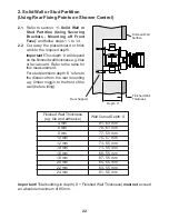
1.5
Fit the supply pipework (Hot - Left,
Cold - Right). The pipework must
project 18 mm from the finished wall
surface at 153 mm centres (use the
installation template as a guide).
Note!
If the connections are reversed,
complete the installation then refer to
section:
‘Reversed Inlet Supplies’
before commissioning.
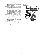
1.6
Loosen the Grubscrew with the
2.5 mm hexagon key (supplied)
and remove the Backplate from the
Shower Control.
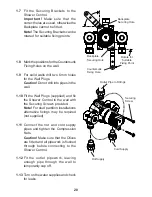
1.7
Secure the Backplate to the wall
using the Fixing Screws (supplied).
Note!
The Grubscrew should be at
the bottom.
1.8
Fit the Concealing Plates.
Note!
Apply silicone sealant to the
back face of the flange.
18 mm
Grubscrew
Содержание DISCOVERY
Страница 42: ...42 NOTES ...
Страница 43: ...43 NOTES ...


