


14. Release jack pressure and reposition the dial indi-
cator to the opposite side of the crown. Indicate to
the top of the crank sprocket of crankshaft exten-
sion. Set the indicator dial to “0” reading.
15. Energize the hydraulic jack and apply enough pres-
sure to support the slide assembly and crankshaft.
16. The reading on the indicator dial now is the main
bearing clearance on the side opposite the flywheel
(or main gear) of the press. Record this reading.
17. Add the clearances obtained in Steps 12 and 16
above. Divide this result in half to determine the
average main bearing clearance. Record this
reading.
18. Release jack pressure and place the dial indicator
on the frame near the connection. Indicate to the
flat on the clamp screw or a similar fixed point on
the connection. Set the indicator dial to “0” reading.
19. Energize the hydraulic jack and apply enough pres-
sure to support the slide assembly and crankshaft.
20. Subtract the reading recorded in Step 17 from the
reading currently displayed on the indicator. This
difference is the clearance between the connec-
tion bushing and crankshaft.
21. Determine the ball box clearance by subtracting
the clearances obtained in Steps 17 and 20 above
from the total bearing clearance.
22. This completes the slide individual bearing clear-
ance checks. Remove the hydraulic jack and dial
indicator from the press. Reinstall any covers
which were previously removed from the press.
Tighten the associated mounting screws securely.
MAIN BEARINGS
AND CONNECTION BEARINGS
Precise fitting and checking of bearings during assem-
bly of the press helps assure long and trouble-free
bearing life, provided they are lubricated properly and
the press is not overloaded. A check of bearing clear-
ances should be made at least every six (6) months,
depending upon the press application and environ-
mental conditions. This check should be made to deter-
mine if any excessive wear has taken place.
BUSHING FITTING PRACTICE
If a check of bearing clearances reveals the need to
replace the main or connection bushings, it is most
important that the recommended fitting practice be
observed. These bushings are split and must be pre-
loaded by squeezing them in the bore with the bearing
cap. The outside diameter of the bushing is made
approximately .002” to .003” (0.05 to 0.07 mm) larger
than the bore of the associated part. Therefore, after
the bushing is installed, the bearing cap must be drawn
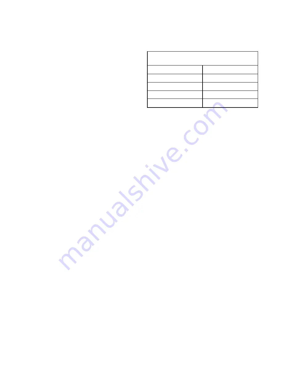
down the prescribed amount. The chart below shows
the required torque values of cap screws for the related
bearings.
After the bearing cap is fully seated and properly
torqued, the bushing bore should be checked with a
bore gauge at several places. Then compare that bore
with the diameter of the mating shaft and make cor-
rections, if necessary, to achieve the proper running
clearance.
SPLIT MAIN AND
CONNECTION BUSHINGS
Connection Bushing — Replacement connection
bushings, available from Minster, will normally have
additional stock allowed in the bore so that the bore can
be honed with the bushing torqued in assembly with its
mating connection. This method is preferred for accom-
plishing precise fit.
Connection bushings may also be ordered with the
bores machined for the proper running clearance, but
the bushing may still have to be honed for proper fit
after it is installed and torqued in the connection
assembly. When ordering new connection bushings,
please advise the Minster Repair Parts Department
whether bushings should be furnished with or without
honing stock.
NOTE: If bushings must be honed, make certain a
“jump” hone is used because of the axial type
oil spreader grooves in the bore.
Main Bushings — Replacement main bushings, avail-
able from Minster, are normally supplied with bores
machined to provide proper running clearance. Further
honing, scraping, or fitting is seldom required; howev-
er, make certain the bore of the new bushing is correct
for the application. Bore must be checked with a bore
gauge to assure proper clearance.
G - 6
Torque Values For Main And Connection
Bearing Cap Screws
PRESS SIZE
CAP SCREW TORQUE
No. 4 - 101
110 lb-ft (149 N-m)
No. 5 - 101
200 lb-ft (271 N-m)
No. 6 - 101
200 lb-ft (271 N-m)
No. 7 - 101
430 lb-ft (583 N-m)
Содержание IOI
Страница 1: ...Manual No 1010C MINSTER 8952 399 15 00 Service Manual OBI OBS SERIES PRESS MODEL...
Страница 2: ...Manual No 1010C MINSTER 8952 399 15 00 Service Manual OBI OBS SERIES PRESS MODEL...
Страница 9: ......
Страница 25: ......
Страница 51: ......
Страница 63: ......
Страница 85: ...I 8 COMMENTS CORRECTIVE STEPS TAKEN Inspected By Press approved for operation Press NOT approved for operation...
Страница 87: ...I 10 COMMENTS CORRECTIVE STEPS TAKEN Inspected By Press approved for operation Press NOT approved for operation...
Страница 89: ...I 12 COMMENTS CORRECTIVE STEPS TAKEN Inspected By Press approved for operation Press NOT approved for operation...
Страница 90: ...ADDITIONAL COMMENTS I 13...


