


connection caps are reassembled. A chart of recom-
mended torque values for the cap screws used to
secure the main and slide connection bearing caps is
provided in the “Torque Value Chart” on page G-6.
Apply grease lubricant under the heads of these
screws and install hardened flat washers. Then apply
Loctite Adhesive Grade 242 (Blue Liquid) to the screw
threads, install the screws, and tighten them to the rec-
ommended torque value.
If bushings are being replaced in the slide connection
bearings, please refer to the recommended bushing fit-
ting procedures outlined on page G-6.
WARNING
MAKE CERTAIN THE SLIDE IS SUPPORTED BY
ADEQUATE BLOCKING BEFORE DISASSEMBLING
THE CONNECTION CAPS.
SLIDE BALL BOX
After extended use, clearance in the slide ball box will
increase due to wear. A threaded adjusting nut is
included as part of the assembly so that the recom-
mended clearance can be restored via a simple adjust-
ment. Ball box clearance must be checked every six (6)
months under normal operating conditions.
To Check Slide Ball Box Clearance:
1. Remove dies or tooling from the press.
2. Turn ON the air supply to the press. Charge the
counterbalance cylinder (if applicable) with air pres-
sure that is at least equal to the amount shown for
“0” die weight.
3. Place the POWER, OFF-ON-BAR Selector Switch
in the ON position.
4. Start the main drive motor. Make certain that oil is
dripping from the gibs.
5. Place the Stroking Selector Switch in the INCH
position. Then position the slide at Bottom Dead
Center (BDC) of the stroke.
WARNING
MAKE CERTAIN THAT ALL PERSONS ARE
CLEAR OF ANY PINCH POINTS ASSOCIATED
WITH THE OPERATION OF THE PRESS AND/OR
ITS AUXILIARY EQUIPMENT.
6. Stop the main drive motor. Place the Stroking
Selector Switch in the OFF position. Make certain
that the flywheel has stopped turning completely.
Attach a WARNING sign to the press controls to
warn other personnel that the press is currently
being serviced.
WARNING
MAKE CERTAIN THAT POWER IS DISCONNECTED
FROM THE MAIN DRIVE MOTOR AND THAT THE
FLYWHEEL HAS STOPPED TURNING BEFORE
PROCEEDING.
7. Exhaust air from slide counterbalance cylinder (if
provided).
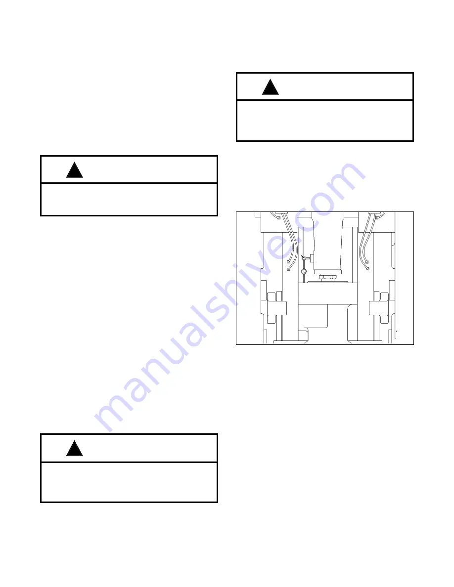
8. Place a base mounted dial indicator on the side of
the connection assembly. Position the dial indica-
tor so that its spindle contact point is perpendicu-
lar to the top of the slide. (See Figure 6F.)
9. Place a hydraulic jack between the slide face and
the bed (or bolster). Place the jack directly under
the connection screw.
NOTE: To prevent damage to slide and bed (or
bolster), place flat steel plates between
jack and slide, and between jack and bed
(or bolster).
10. Energize the hydraulic jack and apply enough
pressure to support the slide assembly.
NOTE: Applied jack pressure should never
exceed 5 percent of press rated tonnage.
11. The reading on the indicator dial now is the ball
box clearance. Apply and release jack pressure
several times until consistent readings are
obtained. If readings exceed .003” (0.0762 mm),
the ball box requires adjustment.
F - 7
!
!
!
Figure 6F. Checking slide ball box clearance.
Содержание IOI
Страница 1: ...Manual No 1010C MINSTER 8952 399 15 00 Service Manual OBI OBS SERIES PRESS MODEL...
Страница 2: ...Manual No 1010C MINSTER 8952 399 15 00 Service Manual OBI OBS SERIES PRESS MODEL...
Страница 9: ......
Страница 25: ......
Страница 51: ......
Страница 63: ......
Страница 85: ...I 8 COMMENTS CORRECTIVE STEPS TAKEN Inspected By Press approved for operation Press NOT approved for operation...
Страница 87: ...I 10 COMMENTS CORRECTIVE STEPS TAKEN Inspected By Press approved for operation Press NOT approved for operation...
Страница 89: ...I 12 COMMENTS CORRECTIVE STEPS TAKEN Inspected By Press approved for operation Press NOT approved for operation...
Страница 90: ...ADDITIONAL COMMENTS I 13...


