5
Wiring method
The cables are available in both straight type and right angle type. A right angle type
connector is attached facing left (towards the SUP port). The direction of the straight type
arrow is aligned with socket latch.
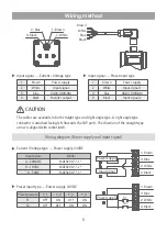
Wiring diagram (Power supply and input signal)
1:
Brown
3:
Blue
2:
White
4:
Black
1:
Brown
3:
Blue
2:
White
4:
Black
Brown
White
Blue
Black
3: Blue
1: Brown
2: White
4: Black
Current / Voltage type — Power supply 24VDC
Preset input type — Power supply 24VDC
Input signal
Model
4~20mADC
MAER200-*-*-1*
0~10VDC
MAER200-*-*-2*
0~5VDC
MAER200-*-*-3*
Preset pressure
P_1
P_2
P_3
P_4
S1
OFF
ON
OFF
ON
S2
OFF
OFF
ON
ON
S1
S2
Input signal
Power supply
Power supply
CAUTION
Input signal — Preset input type
1
2
Input signal 1
GND(COMMON)
Power supply
3
Input signal 2
4
Input signal — Current / Voltage type
1
2
White
Input signal
Blue
GND(COMMON)
Brown
Power supply
3
Black
White
Blue
Brown
Black
Monitor output
4

