background image

3-2

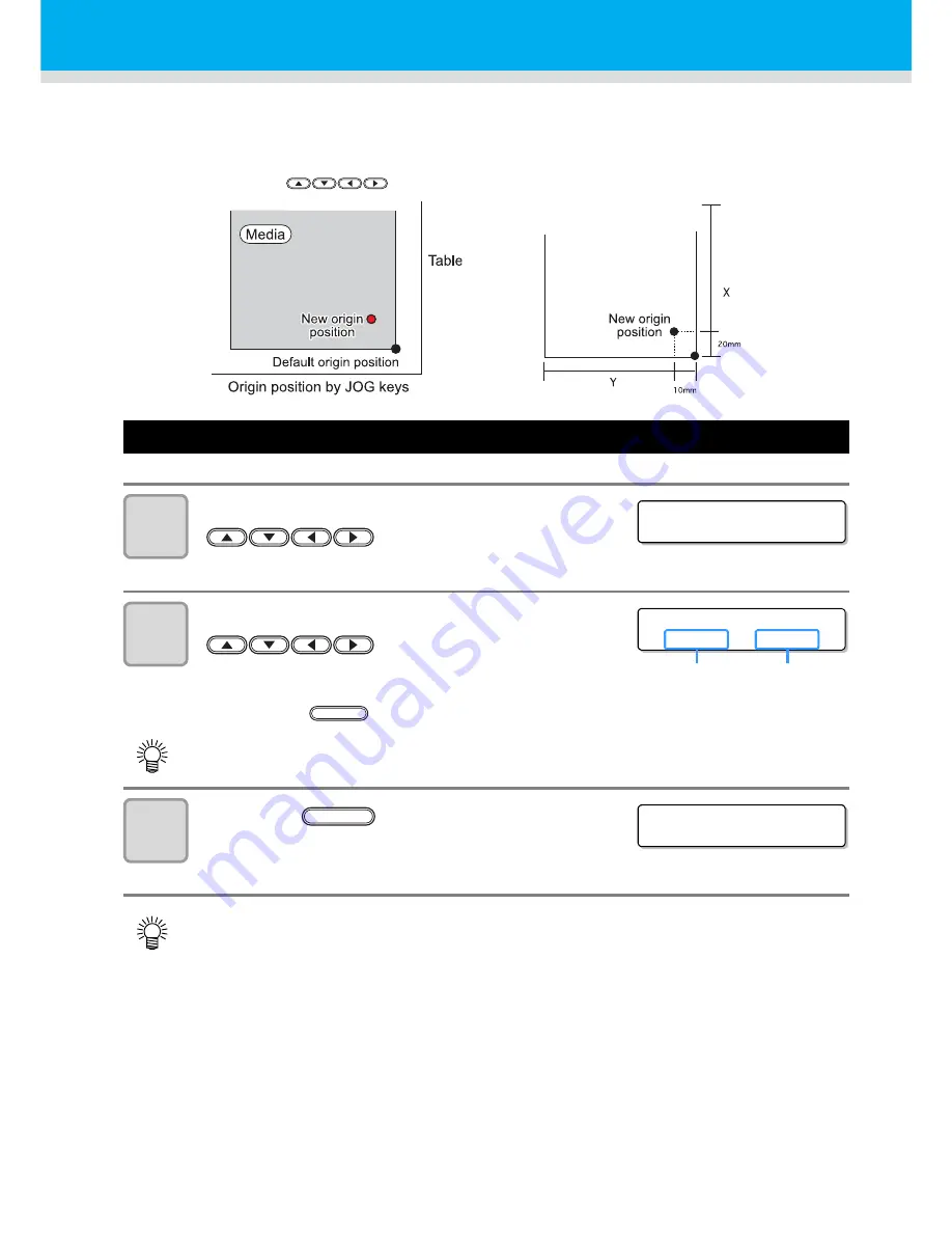
Changing origin 

The default origin position can be changed.
There are following 2 changing methods.

Changing origin with JOG keys

1

when <LOCAL> is displayed, press the 

 keys.

• Origin setup screen is displayed.

2

Move the head and table with the 

 keys.

• Move the head to the origin setting position to set

the origin.

• Press the 

 key to display the table height set screen.

3

Press the 

 key when the 

drawing origin is determined.

• The origin is changed.

• Set the origin in accordance with the ORIGIN marks on the machine.

• The origin set here is cleared by turning the power off.

Changing with the JOG keys 

Changing with the “ORIGIN” 

in the FUNCTION menu

< L OC A L . 1 >

OR I G I N S E T U P

6 0 0 . 0

7 0 0 . 0

Origin position 

(back and forth)

Origin position 

(right and left)

TABLE

OR I G I N S E T U P

* * OR I G I N * *

ENTER

Содержание UJF-706

Страница 1: ...D202102 20 MIMAKI ENGINEERING CO LTD URL http eng mimaki co jp is ...

Страница 2: ...Side 1 4 Rear Side of the main power switch 1 5 Operation Panel 1 6 Carriage and UV irradiation device 1 7 Wiper 1 7 Flushing Box 1 7 Emergency Switch 1 8 UV power supply 1 8 Connecting the cables 1 9 Connecting the USB2 0 interface cable 1 9 Connecting the power cable 1 9 UV Irradiation Device and Indicator 1 10 UV irradiation device 1 10 Function of indicator 1 10 Setting the ink cartridge 1 11 ...

Страница 3: ...ing the drawing 2 19 When drawing stops 2 19 Use the Copy Function 2 20 Subtank Maintenance 2 20 About covers 2 21 CHAPTER 3 Useful Function Changing origin 3 2 Changing origin with JOG keys 3 2 Changing origin with FUNCTION menu 3 3 Adjusting head gap 3 4 Selecting for head gap adjustment 3 4 Checking head gap 3 5 When nozzles missing can not be improved 3 6 Alternative nozzles for printing when ...

Страница 4: ...lear 3 34 Displaying the information of this machine 3 35 CHAPTER 4 How to care Maintaining 4 2 When this machine is left unused for a long time 4 2 Precautions in cleaning 4 2 Cleaning exterior surfaces 4 3 Ink cartridge 4 4 Replacing with a new ink cartridge 4 4 Ink cartridge trouble 4 5 Washing cartridge 4 6 Cleaning the flushing box 4 7 Avoiding ink dripping at printing 4 10 When the waste ink...

Страница 5: ...eplacing UV lamp 4 38 Setting the UV lamp OFF duration 4 38 About replacing UV lamp 4 38 Resetting UV lamp irradiation duration 4 39 Checking method of UV illumination intensity 4 40 Check the UV illumination intensity 4 41 Cleaning of the Ionizer 4 45 Prevent the nozzle clogging of spot color 4 47 CHAPTER 5 In Case of Trouble Check first when a trouble occurred 5 2 The power is not turned on 5 2 ...

Страница 6: ...vi CHAPTER 6 Appendix Specifications 6 2 Basic unit specifications 6 2 Specifications for ink 6 3 Position of the warning label 6 4 Function Flowchart 6 6 ...

Страница 7: ...vii ...

Страница 8: ... equipment is operated in a commercial environment This equipment generates uses and can radiate radio frequency energy and if not installed and used in accordance with the instruction manual may cause harmful interference to radio communications Operation of this equipment in a residential area is likely to cause harmful interference in which cause the user will be required to correct the interfe...

Страница 9: ...r I and subchapter J indicates compliance with the CDRH regulations and is labeled on the product when marketed in the United States This Model is equivalent to Class II laser device according to CDRH Regulation This product complies with 21 CFR chapter I and subchapter J Use of controls adjustments or performance of procedures other than those specified in this manual may results in hazardous rad...

Страница 10: ...ry to keep this Operation Manual on hand Make arrangements to deliver this Operation Manual to the person in charge of the operation of this device This Operation Manual has been carefully prepared for your easy understanding however please do not hesitate to contact a distributor in your district or our office if you have any inquiry Description contained in this Operation Manual are subject to c...

Страница 11: ...on of the plotter The symbol indicates helpful information that will facilitate the use of the device Indicates the reference page for related contents The symbol indicates the case where some phenomenon that requires a CAUTION sign including DANGER and WARNING signs exists A concrete precaution precaution against an electric shock in the case of the sketch given on the left is shown in the illust...

Страница 12: ...device When cleaning the ink station or the head be sure to wear the supplied goggles and gloves since you may get ink or cleaning solution in your eyes If anyone drinks ink or washing liquid in mistake get the person to vomit and see a doctor immediately Do not allow him or her drink vomit Then contact the Poison Control Center If you absorb a lot of vapor and feel bad immediately move to a locat...

Страница 13: ... where the device produces smoke or unpleasant smell fire or electric shocks can result Be sure to turn off the power switch immediately and detach the plug from the receptacle Check first to be sure that the device no longer produces smoke and contact a distributor in your district for repair Never repair your device by yourself since it is very dangerous for you to do so Grounding work This unit...

Страница 14: ...e glass fragments tobe scattered Never look at the UV lamp being lit with your naked eyes or it may cause pain in your eyes or visual impairment Be sure to wear safety glasses Do not apply ultraviolet UV light directly to your skin or it may cause irritation on your skin Be sure to use only the UV lamp recommended by Mimaki or it may cause fire or damages to the unit Never use UV lamps other than ...

Страница 15: ...the room temperature for three hours or more before using it Open the ink cartridge just before installing it in the printer If it is opened and left for an extended period of time normal printing performance of the printer may not be ensured Make sure to store ink cartridges in a cold and dark place Be sure to thoroughly consume the ink in the ink cartridge after opened If an extended period of t...

Страница 16: ...sonnel or fire In order to prevent accidents from occurring be sure to carry out periodic inspections and replacement of time change components About firing and smoking Touching hot parts such as the UV irradiation device with combustible materials may cause firing and or smoking Leaving combustible materials under the UV irradiation device for a couple minutes may also cause firing and or smoking...

Страница 17: ...A place that is not horizontal A place in which temperature and humidity vary by a great margin Use the device under the following environment Operating environment 15 30 35 65 Rh A place that vibrates A place exposed to direct air blow from air conditioner etc A place where fire is present ...

Страница 18: ...ad This Operation Manual This manual provides the explanation about the displayed characters and used keys on the Display Panel in addition to the operation procedures Proceed operations confirming them while using ...

Страница 19: ...nd UV irradiation device 1 7 Wiper 1 7 Flushing Box 1 7 Emergency Switch 1 8 UV power supply 1 8 Connecting the cables 1 9 Connecting the USB2 0 interface cable 1 9 Connecting the power cable 1 9 UV Irradiation Device and Indicator 1 10 UV irradiation device 1 10 Function of indicator 1 10 Setting the ink cartridge 1 11 Available Ink Type 1 11 About handling of ink 1 11 About Washing Cartridge for...

Страница 20: ...e and a space required for drawing Width Lengh Height Total Weight 2500 mm 1750 mm 1550 mm Approx 500 kg If the place to install the machine is exposed to strong sunlight around the window draw a curtain to prevent the machine from being exposed to strong sunlight 500 mm or more 1000 mm or more 3500 mm or more 3750 mm or more 1000 mm or more 500 mm or more ...

Страница 21: ...red to move on the step free same floor 1 Lift the adjuster foot 2 Push the circled position shown on the right figure and move this machine For safety be sure to work it with more than 2 persons Do not push the cover to move this machine since the cover may be deformed 3 Move the adjuster foot downwards When moving this machine take care not to give a significant impact on it After moving this ma...

Страница 22: ...uum is ON Ink Station Each color of ink cartridge are in it Operation Panel The operation keys to set this machine and the display are on it P 1 6 Power Switch Turns on off the power of this machine Stand Supports the main body Casters to move are on it Emergency switch Press in the event of an emergency The power is forcibly cut to stop unit operation P 1 8 Indicator Indicating a state of the mac...

Страница 23: ...h USB Connector USB2 0 compliant interface connector Main Power Switch 1 Turns on off the power of this machine except UVLamp AC Inlet Inlet 1 Connects the power cable Water Heating Device Keeps the ink at a proper temperature UV power supply Supplies power for the UV lamp P 1 8 ...

Страница 24: ...ION END Display Displays the status of this machine set items and errors ACTIVE lamp Blinks in receiving or drawing data key Switches REMOTE and LOCAL key Moves to the next menu or sets the inputs REMOTE ENTER key Press to switch over ON OFF of the vacuum key Draws test patterns to check if there are any drawing failures such as ink clogging key Displays function UV menu VACUUM UV key When you wis...

Страница 25: ...ferent Wiper The wiper on the right front side of this machine removes the ink attached on the head at ink filling or clean ing Flushing Box A flushing box is placed in the left of this machine When the print head flushes waste ink is absorbed by the flushing filter in the flushing box Replace the flushing filter with a new one frequently P 4 7 Do not expose your naked eyes directly to the light i...

Страница 26: ...en stopping the machine for safety reason press the switch Emergency stop switches are located on upper part of the machine on two places UV power supply The UV power supply located at the lower left of this machine works with the UV irradiation device ...

Страница 27: ...led USB hard disk drive the data output speed to this machine may drop That can cause the head unit to stop temporarily at the right or left end during printing Connecting the power cable Your RIP is required to support USB2 0 interface If USB2 0 interface is not installed in your computer ask a RIP vender near you or our branch office Use only the supplied power cable Be sure to connect the power...

Страница 28: ...ng disabled UV lamp being cooled 5 minutes The UV lamp goes OFF in the following cases When operation for setting the UV lamp OFF is executed When 30 minutes or more have elapsed after drawing When an error has occurred in this unit After the UV lamp has been set OFF it is cooled The UV lamp cannot be set ON again and this unit cannot start drawing Wait for going the light OFF for a while Blinking...

Страница 29: ... condition shake ink according to the procedures in the next page About white ink refer to the Chapter 4 and perform the periodical maintenance work P 4 21 Ink Type Color SPC 0371 Ink Magenta Cyan Yellow SPC 0404HY included Black White Light Magenta Light Cyan Clear SPC 0516 Ink K 200 Magenta Cyan Yellow Black White Light Magenta Light Cyan Cleaning solution 1 1 It is used for cleaning the head an...

Страница 30: ...he cartridge with paper towels Then shake it more than twenty times right and left so that ink flows inside the cartridge If you shake it too strong the pack inside may be damaged and it may cause ink leakage Therefore perform this carefully If the remaining amount of ink is less ink in the cartridge cannot be beaten enough Tilt the cartridge until it becomes vertical Wrap the tip with paper towel...

Страница 31: ...ng page P 4 4 Replacing with a new ink cartridge Confirm the ink slot number and insert the ink cartridge of the correct color 4 colors ink set white W clear S 4 colors ink set white W 6 colors ink set white W 6 colors ink set white W clear S 1 M Magenta C Cyan Y Yellow K Black W White S Clear Lc Light Cyan Lm Light Magenta Reserved 1 2 7 8 5 6 c d 3 4 a b Ink slot No Ink slot No 1 2 3 4 5 6 7 8 a...

Страница 32: ...the cartridge drawing quality would be poor Store ink cartridges in a place that is out of the reach of children When discarding unused ink cartridges entrust them to an industrial waste disposal contractor clarifying their contents Some component photoinitiator of the ink is toxic against aquatic organisms Avoid leakage of it to natural water system or domestic waste water Do not use ink cartridg...

Страница 33: ...fore Use About Washing Cartridge for Hard Cleaning Set the dedicated washing cartridge into the mounting slot Use a genuine washing cartridge Use in the proper way in conjunction with the head maintenance method ...

Страница 34: ...liber of the core 2 inches or 3 inches Print face Outer surface of the roll media End of the roll media Attach with a tape or a weak adhesive on the core Expansion and contraction of the media Do not use sheet types of media immediately after unpacking The media can expand and contract due to room temperature and humidity The media have to e left in the atmosphere in which they are to be used for ...

Страница 35: ... the key to set each function of the UV lamp Check the remaining amout of ink the model name the firmware version and so on with the the key Switch between REMOTE and LOCAL with the key Erase the drawing data that this machine has received with the key Press the key to switch ON OFF of the vacuum By pressing the key and then the jog key you can move the table up and down REMOTE When REMOTE is disp...

Страница 36: ...1 18 ...

Страница 37: ...ozzle dropout while power off 2 9 Setting media 2 11 Changing the height of the table 2 12 Test drawing 2 13 Head cleaning 2 14 Cleaning by Normal 2 14 Cleaning by Hard 2 15 Cleaning by Wiping 2 16 Cleaning by Hard2 2 17 Drawing an image from data 2 18 Starting the drawing 2 18 Cancelling the drawing 2 19 When drawing stops 2 19 Use the Copy Function 2 20 Subtank Maintenance 2 20 About covers 2 21...

Страница 38: ...2 2 Operation flow 1 Turning the power on 2 Setting media 3 Head cleaning 5 6 See Turning the power ON OFF P 2 4 See Setting media P 2 11 See Head cleaning P 2 14 ...

Страница 39: ...peration flow 2 3 2 Basic Operations 4 Head cleaning 5 Drawing an image from data 6 Turning the power off See Head cleaning P 2 14 See Drawing an image from data P 2 18 See Turning the power ON OFF P 2 4 ...

Страница 40: ...lights in green and when it is OFF the light is out 1 Turn the UV power supply switch ON on the side of this machine Press the switch to I side 1 Turn the main power switch 1 and 2 ON on the side of this machine Press the switch to I side 2 Turn the power ON with the power switch Press the power switch on the front of this machine When the power is turned on the firmware version is displayed This ...

Страница 41: ...2 5 Turning the power ON OFF 2 Basic Operations 3 LOCAL appears 4 Turn the power of the connected computer ON LOCA L 1 ...

Страница 42: ...s the key If you press the key cleaning is cancelled and the screen becomes LOCAL display 2 When water becomes hot enough cleaning starts automatically When the cleaning is completed LOCAL is displayed If ERROR149 occurred at the previous startup If ERROR149 INK UPSTREAM GRD occurred at the previous startup perform the operation below 1 Perform wiping to remove ink drop on the nozzle surface When ...

Страница 43: ...certain amount of time has passed the hot water temperature does not reach a certain temperature a message is displayed on the screen When you select CONTINUE the system will wait until the hot water temperature reaches a certain temperature When you select END the status becomes available for drawing If you perform drawing with the hot water temperature not reaching a certain temperature the imag...

Страница 44: ... standby position on the left of this machine Any error occurs P 5 6 Error message 1 Turn the power of the connected com puter OFF 2 Turn the power OFF with the power switch Do not turn the main power switch off on the side of this machine When using this machine next time light the green lamp with the power switch When the power supply switch is pressed while the UV lamp is lighting after the UV ...

Страница 45: ...e cleaning and the flushing when SLEEP MAINTE P 4 19 is selected When finishing the maintenance the power is turned off automatically Do not turn off the power switch at startup from the sleep mode When the sleep operation has been completed the machine turns off the power switch automatically Until two hours have passed after the power switch was turned off the machine starts every 10 min When tw...

Страница 46: ...ition other than the waiting position Turning the power off when the head does not return to the position in readiness the left side may dry the head and may cause nozzle clogging In this case turn the power ON again confirm that the head has returned to the position in readiness the left side then turn the power OFF Do not turn the power OFF in drawing The head may not return to the position in r...

Страница 47: ...urface and the filter of the cooling fan Also the reflection from the UV light becomes higher In case the adhered ink is cured or get sticky by the UV light reflection it causes nozzle clogging and mismatched ink position Sometimes it may be necessary to replace the head due to the failure If within the absorption area there are suction holes not closed by the media close such suction holes placin...

Страница 48: ...AL is displayed press the key 2 Raise or lower the table with the key Raises the table Lowers the table Press the key to display the origin setup screen 3 Press the key Press the key to set the value on the origin setup screen as the origin position L OCA L 1 TABLE T AB L E HE I GH T SE T H 1 5 0 0mm TABLE END ENTER ...

Страница 49: ...osition P 3 2 When the following message is displayed it cannot print Start drawing after the message has disappeared WATER NOT READY The water temperature in the water heating device has not reached the predetermined value Check before starting test drawing Is media set P 2 11 Is the origin position set P 3 2 Is the head gap value registered P 3 16 Is the checking method of the gap adjustment set...

Страница 50: ...rawing and check the pattern P 2 13 Repeat cleaning and test drawing until the drawn pattern becomes normal Normal Select this when there is a dozen line missed on the test pattern P 2 14 Wiping Select this when there are several lines missed on the test pattern The wiper wipes P 2 16 Hard At the end of daily work clean the head with washing liquid not to cure the mist adhered to the nozzle and th...

Страница 51: ...starts When the cleaning is completed LOCAL is displayed 5 Execute the test drawing and check the pattern P 2 13 Repeat cleaning and test drawing until the drawn pattern becomes normal Performing the hard cleaning at end of the day s work prevents the nozzle clogging With one cartridge of washing liquid hard or hard2 cleaning can be performed once a day for about one month If the washing liquid ca...

Страница 52: ... key 6 Press the key Cleaning starts When the cleaning is completed LOCAL is displayed 7 Execute the test drawing and check the pattern P 2 13 Repeat cleaning and test drawing until the drawn pattern becomes normal When the print quality is not improved after repeating head cleaning clean the wiper and the cap See P 4 26 Wiper cleaning If the print quality is not improved after cleaning the wiper ...

Страница 53: ...ng is displayed 4 Press the key Cleaning starts When the cleaning is completed LOCAL is displayed 5 Execute the test drawing and check the pattern P 2 13 Repeat cleaning and test drawing until the drawn pattern becomes normal With one cartridge of washing liquid hard or hard2 cleaning can be performed once a day for about one month If the washing liquid cartridge cannot be used because NO CARTRDG ...

Страница 54: ...e of the water heating system has not reached the predetermined value a message is displayed Drawing is not allowed in such cases When the display is disappeared drawing can be started Data can be sent even if both errors are displayed Drawing starts after the errors are disappeared If you perform drawing with the hot water temperature not reaching a certain temperature the right message is displa...

Страница 55: ...he machine stops drawing and returns to the local mode Press the key in the local mode to restart drawing Message Cause Solution The carriage detected an obstacle Remove the obstacle on the table 1 1 For some detecting conditions the machine finishes drawing and performs initial operation The area sensor detected an obstacle When an obstacle was detected the table automatically lowers to avoid it ...

Страница 56: ...th the key and press the key 3 Select the SUBTANK MAINTE with the key and press the key 4 Set execution of subtank maintenance and press the key 1 Select the head with the key 2 Select execution of subtank maintenance with the key If Error 148 occurs an appropriate head is selected Press key 5 Press the key Subtank maintenance starts In case that you use this function you need RasterLinkPro5 ver 2...

Страница 57: ...uring drawing the message is displayed Stop the drawing 2 Stop the data transmission from the computer 3 Close the cover 4 Press the key 5 The carriage will start to move The same initial operation as that when the power supply is turned on is performed Do not open the right and the left covers during drawing If you open the cover during drawing drawing will be stopped and you cannot continue it M...

Страница 58: ...2 22 ...

Страница 59: ...Setting the print method 3 14 Registering head gap value 3 16 Set the scan width of the head 3 17 Changing the UV illumination intensity 3 19 Sets UV irradiation at starting ending of drawing 3 20 Setting the priority 3 21 Sets the cooling time per scan 3 22 Initializing the settings 3 23 Turning OFF the UV lamp 3 24 Selecting for head gap adjustment 3 24 Setting the UV lamp OFF duration 3 25 Chan...

Страница 60: ...to set the origin Press the key to display the table height set screen 3 Press the key when the drawing origin is determined The origin is changed Set the origin in accordance with the ORIGIN marks on the machine The origin set here is cleared by turning the power off Changing with the JOG keys Changing with the ORIGIN in the FUNCTION menu L OCA L 1 OR I G I N S E T UP 6 0 0 0 7 0 0 0 Origin posit...

Страница 61: ...ition of X axis The value in the parentheses indicates the distance from the origin to the maximum effective area 4 Select the Y OFFS by pressing the or keys and press the key 5 Input value by pressing the or keys and press the key Setting the origin position of Y axis The value on the first line indicates the distance from the origin to the maximum effective range 6 Press the key several times to...

Страница 62: ...andcopy printing Continue mode It is on the right front side of this machine Normally use this switch to turn the power ON OFF When the power is ON the power switch lights in green and when it is OFF the light is out 1 When LOCAL is displayed press the key 2 Select GAP CHECK with the key and press the key 3 Select CHECK SELECT with the key and press the key 4 Select mode with the key and press the...

Страница 63: ...the front cover 5 After setting a media press the key The head gap adjustment is performed automatically The head gap is the value set in the screen of P 3 16 6 When the message on the right is displayed close the front cover When continue mode has been selected the head gap adjustment is performed once during printing after turning on the main power Make sure to adjust the head gapfor the gap che...

Страница 64: ... 70 81 90 101 110 121 130 141 150 161 170 181 190 201 210 221 230 1 10 21 30 41 50 61 70 81 90 101 110 121 130 141 150 161 170 181 190 201 210 221 230 1 10 21 30 41 50 61 70 81 90 101 110 121 130 141 150 161 170 181 190 201 210 221 230 1 10 21 30 41 50 61 70 81 90 101 110 121 130 141 150 161 170 181 190 201 210 221 230 1 10 21 30 41 50 61 70 81 90 101 110 121 130 141 150 161 170 181 190 201 210 22...

Страница 65: ...ard speed 1200x1200 8Pass Double speed 6 color ink set 600x600 4Pass Standard speed 600x600 8Pass Double speed 1200x1200 8Pass Standard speed 1200x1200 16Pass Double speed When you use white ink and clear ink print on the clear film to check Nozzle recovery function is invalid when performing test drawing and printing media com pensation pattern NOZ Z L E RCVR NOZ Z L E 1 K N o 1 OF F Registration...

Страница 66: ...key and press the key 4 Select the INIT by pressing the key 5 Select the Nozzle line that needs clear the setting value by pressing or key Press the key the contents set for all nozzle lines are deleted 6 Press the key 7 Press the key several times to end the setting L OCA L FUNCTION F UNC T I ON MA I N T ENANCE EN T ENTER MA I N T ENANCE NOZ Z L E RCVR EN T ENTER NOZ Z L E RCVR I N I T DRAW NOZ Z...

Страница 67: ... printing 1 When LOCAL is displayed press the key 2 Press the key 3 Select the type 1 to 4 with the key and press the key 4 Select the item and set As for setting items see 3 11 Setting list L OCA L 1 FUNCTION F UNC T I ON SE T UP EN T ENTER SE T UP SE L ECT T YPE 1 ENTER ...

Страница 68: ...ing item with the key and press the key Select the item referring to the setting list 5 Select an item with the key and press the key Select the item referring to the setting list 6 Press the key to finish Set items are not cleared even after turning the power off L OCA L 1 FUNCTION F UNC T I ON SE T UP EN T ENTER SE T UP SE L ECT T YPE 1 ENTER 1 I NK L AYERS e n t ENTER 1 I NK L AYERS S E T UP 1 ...

Страница 69: ...ia right and the left posi tions LEFT 1 to 700 mm RIGHT 0 to LEFT mm Set the media position UV LEVEL P 3 19 HIGH STANDARD LOW NONE NO PRINT H NO PRINT N NO PRINT L Sets the UV light intensity UV SCAN ADD P 3 20 OFF 1 to 9 Sets UV irradiation at starting ending of drawing INK LAYERS 1 to 9 Prints with layers COOLONG TIME P 3 22 0 0 to 2 0s Sets the cooling time per scan REFRESH LEVEL 0 1 2 3 Refres...

Страница 70: ...nt origin at the end of MEDIA COMP Then the roll media in the rear of this machine will slack Before printing take up the slack in the roll media by hand A slack may cause an inferior image quality When using the take up device set the media first perform MEDIA COMP and draw images Two bands are printed as the compensation pattern Adjust so that the boundary between two bands becomes equal density...

Страница 71: ...e compensation pattern then input the correction value with the or key A space between two lines widens A spacing between two lines narrows The band moves by approx 0 1mm each time changing the correction value by 10 7 Press the key to finish 1 MED I A COMP e n t ENTER 1 MED I A COMP AD J UST 0 END ...

Страница 72: ...lect a setting item with the key and press the key As for setting items see the list on the next page 6 Select an item with the key and press the key As for the items see the list on the next page 7 Press the key to finish L OCA L 1 FUNCTION F UNC T I ON SE T UP EN T ENTER SE T UP SE L ECT T YPE 1 ENTER 1 PR I N T MODE e n t ENTER 1 PR I N T MODE QUA L I T Y e n t ENTER 1 PR I N T MODE QUA L I T Y...

Страница 73: ... the print method 3 15 3 Useful Function Item Description QUALITY STANDARD Standard drawing quality FINE High quality drawing drawing speed is slower FAST High speed drawing image quality is slightly inferior ...

Страница 74: ...elect the HEAD GAP with the key and press the key 5 Input the head gap value with the key and press the key Setting Value 0 9 to 2 0 mm 6 Press the key to finish If a proper value was not set to the head gap value it may have an influence on drawing quality due to ink falling in big drops etc on the media during drawing L OCA L 1 FUNCTION F UNC T I ON SE T UP EN T ENTER SE T UP SE L ECT T YPE 1 EN...

Страница 75: ...press the key 5 Select the ON with the key and press the key 6 Input the left media position with the key and press the key Setting Value 1 to 700mm 7 Input the right media position with the key and press the key 0 to the set value of LEFT 8 Press the key to finish L OCA L 1 FUNCTION F UNC T I ON SE T UP EN T ENTER SE T UP SE L ECT T YPE 1 ENTER 1 MED I A POS e n t ENTER 1 MED I A POS S E T UP ON ...

Страница 76: ... head the width of image data has a priority Therefore the image data is printed beyond setup scan width Make sure the width of image data is narrower than the setup scan width before printing 1 Printing scan width 2 Printing scan width 2 1 Media Image data Media position right Media position left Table ...

Страница 77: ...sh Item Outline HIGH The UV lamp lights at high light intensity P 3 26 STANDARD The UV lamp lights at normal light intensity P 3 26 LOW The UV lamp lights at low light intensity P 3 26 NONE The UV lamp does not light during drawing NO PRINT H Only the UV lamp lights without drawing Use when curing ink after drawing in case that the UV lamp did not light during drawing NO PRINT N NO PRINT L L OCA L...

Страница 78: ...has ended Supported from the firmware ver 1 80 1 When LOCAL is displayed press the key 2 Press the key 3 Select the type 1 to 4 with the key and press the key 4 Select the UV SCAN ADD with the key and press the key 5 Input the left media position with the key and press the key Setting Value OFF 1 to 9 6 Input the right media position with the key and press the key Setting Value OFF 1 to 9 7 Press ...

Страница 79: ... and press the key 4 Select the PRIORITY with the key and press the key 5 Select the HOST or the PLOT with the key and press the key HOST Setting of the computer has the priority PLOT Setting of this machine has the priority 6 Set other items with the same way Item Print mode Ink layers Cooling time 7 Press the key to finish L OCA L 1 FUNCTION F UNC T I ON SE T UP EN T ENTER SE T UP SE L ECT T YPE...

Страница 80: ...t the type 1 to 4 with the key and press the key 4 Select the COOLONG TIME with the key and press the key 5 Set the cooling time with the key and press the key Setting Value 0 0 to 2 0s 6 Press the key to finish Please do not store combustible materials near the flushing BOX L OCA L 1 FUNCTION F UNC T I ON SE T UP EN T ENTER SE T UP SE L ECT T YPE 1 ENTER 1 COOL I NG T I ME e n t ENTER 1 COOL I NG...

Страница 81: ... 3 Press the key 4 Select the SETUP RESET with the key and press the key 5 Press the key The settings are reset 6 Press the key to finish This initializes only the set items L OCA L 1 FUNCTION F UNC T I ON SE T UP EN T ENTER SE T UP S E L EC T T Y PE 1 ENTER 1 S E T UP RE SE T e n t ENTER 1 SE T UP RE SE T I N I T I A L I Z E OK e n t ENTER END ...

Страница 82: ... is displayed press the key 2 Select LAMP OFF with the key and press the key 3 Press the key Turning OFF operation of the UV lamp starts 4 After the lamp is turned OFF and when the screen on the right is displayed press the key to finish You can set time until the UV lamp is turned OFF P 3 25 No printing is to be carried out long time 30 minutes or more set the UV lampOFF Once the UV lamp is set O...

Страница 83: ...ned OFF 1 When LOCAL is displayed press the key 2 Select OFF TIMER with the key and press the key 3 Press the key to set time until the UV lamp is turned off and press the key 4 Press the key to finish L OCA L 1 UV UV L AMP OF F T I MER EN T ENTER UV OF F T I MER T I ME 0 0 h 3 0m ENTER END ...

Страница 84: ... intensity of light to HIGH and press the key Setting Value Lv 1 to Lv 16 4 Press the key to set the intensity of light to NORMAL and press the key Setting Value Lv 1 to Lv 16 5 Press the key to set the intensity of light to LOW and press the key Setting Value Lv 1 to Lv 16 6 Press the key to finish L OCA L 1 UV UV L AMP SE T UV L EVE L e n t ENTER SE T UV L EVE L H I GH L v 1 6 ENTER SE T UV L EV...

Страница 85: ...IST FAN LOW STANDARD HIGH OFF Setting the strength of rear mist fan TIME SET Setting the present date and time MACHINE NAME 01 99 Setting a machine name machine No for recognizing each machine when plural machines are connected through USB2 0 interface PRINT MODE STANDARD HIGH Setting the print quality INFORMATION SerialNo VERSION ERROR HISTORY MAINTE HISTORY The machine information of the machine...

Страница 86: ...key 3 Select the MIST FAN with the key and press the key 4 Press the keys to change the setting and press the key Setting Value LOW STANDARD HIGH OFF 5 Press the key several times to end L OCA L 1 FUNCTION F UNC T I ON MACH I NE SE T UP EN T ENTER MACH I NE SE T UP M I S T F AN e n t ENTER M I S T F AN S E T UP S T ANDARD ENTER END ...

Страница 87: ...ht hours before the present displayed time When a future time after the present one has been set by mistake performing the following operations in Step 4 enables the already set future time to be restored to the previously set time 1 Press the key in Step 4 2 Press the key If you have made several changes in time setting only the last time to be set can be restored to the previously set time In ad...

Страница 88: ... the key 2 Select the MACHINE SETUP with the key and press the key 3 Select the MACHINE NAME with the key and press the key 4 Select the machine name 01 99 by pressing the key and press the key 5 Press the key several times to end L OCA L 1 FUNCTION F UNC T I ON MACH I NE SE T UP EN T ENTER MACH I NE SE T UP MACH I NE NAME e n t ENTER MACH I NE NAME U J F 7 0 6 0 1 ENTER END ...

Страница 89: ...t the item by pressing the key and press the key As for the items see the list on the below 5 Press the key several times to end Item Description QUALITY STANDARD Draws with the standard speed and the image quality of UJF 706 HIGH Draws slowly to ensure high image quality L OCA L 1 FUNCTION F UNC T I ON MACH I NE SE T UP EN T ENTER MACH I NE SE T UP PR I N T MODE e n t ENTER PR I N T MODE QUA L I ...

Страница 90: ...RSION Displays version information of the machine ERROR HISTORY This displays the history of errors and warnings to date When you press the date of occurrence year month day hour minute and the error warning information are displayed alternately in the order of occurrence Supported from the firmware ver 1 80 MAINTE HISTORY This displays the date and time when the maintenance function was used The ...

Страница 91: ...ion such as F W or the like ERROR HISTORY Supported from the firmware ver 1 80 Displaying the occurrence date Displaying the contents of error MAINTE HISTORY Supported from the firmware ver 1 80 Displaying the contents of maintenance S N D N UJ F 7 0 6 V1 0 0 MRL I I I V1 5 0 ERROR H I STORY 0 0 0 0 1 1 1 1 0 0 1 1 2 1 5 ERROR 4 1 MOTOR Y MA I NTE H I STORY 0 0 0 0 1 1 1 1 0 0 1 1 2 1 5 CARR I AGE...

Страница 92: ... the key and press the key Default is English 4 Press the key to finish Data clear Delete unneccessary data for this machine 1 When LOCAL is displayed press the key 2 Press the key The data is cleared Set item is not cleared even after turning the power off L OCA L 1 FUNCTION F UNC T I ON D I S P L AY EN T ENTER D I S P L AY E n g l i s h e n t ENTER END L OCA L 1 DATA CLEAR DA T A C L E AR EN T E...

Страница 93: ...time is displayed on the left and the right UV LED irradiation time is displayed on the right 3 Press the key to return to LOCAL L OCA L 1 ENTER Remaining amount of ink Version Command information SPC 0 3 7 1 I NK REMA I N 9 9 9 9 9 9 9 9 9 9 9 9 U J F 7 0 6 V 1 0 0 MR L I I I V Pressure information LOCA L 1 NEGA PRES S 2 3 0 k p a Sub Tank information LOCA L 1 S u b T a n k MMMM L L L L F F F F L...

Страница 94: ...3 36 ...

Страница 95: ... 18 Preventing nozzle dropout while power off 4 19 Setting the Refreshing Interval in the Sleep Mode 4 19 Setting the Cleaning Interval in the Sleep Mode 4 20 Regular maintenance of white ink 4 21 If blur or missing remains 4 24 Fill Up Ink 4 24 Subtank Maintenance 4 25 Wiper cleaning 4 26 Refill antifreeze liquid 4 28 Refilling antifreeze liquid 4 29 Cleaning of the UV lamp filter 4 30 Cleaning o...

Страница 96: ...azards or damage to this machine Before starting maintenance work be sure to turn off the main power switch and unplug the power cable otherwise an unexpected accident may occur Do not use benzine thinner or any chemical agent containing abrasives Such materials can deteriorate or deform the surface of the covers Do not apply lubricating oil or the like inside to any part inside this machine Such ...

Страница 97: ...4 How to care Cleaning exterior surfaces If the frame components of the device have stained dampen a poece of soft cloth with water or neutral detergent diluted with water squeeze it and wipe the frame components clean ...

Страница 98: ...idge turning the IC chip side up Display Outline The ink in an ink cartridge is low Drawing can be continued but the ink may end during the drawing Early replacement is recommended The display shown in the left indicates that magenta ink is low The ink in an ink cartridge ended Unable to continue drawing Replace with a new one immediately The display shown in the left indicates that magenta ink en...

Страница 99: ...ouble When all trouble of cartridges are displayed the menu returns to LOCAL Do not leave the ink cartridge unreplaced for a long time This will cause the nozzle clogging and the printer must be repaired by a service person L OCA L 1 C o l o r o f I NK MMCC YYKK WWSS SPC 0 3 7 1 I NK REMA I N 9 9 9 9 9 9 9 9 9 9 9 9 ENTER L OCA L 1 NO CAR TRDG MMCC YY KK WWSS L OCA L 1 I NK NEAREND MMCC YY KK WWSS...

Страница 100: ...Display Outline The washing cartridge has not been inserted Insert the washing cartridge The cartridge that is not the washing cartridge has been inserted The ink IC has an abnormality Insert the correct washing cartridge No washing liquid in the cartridge Insert a new washing cartridge Either of problems above has occurred Return to the LOCAL and check the error contents LOCA L 1 Wa s h Liqu i d ...

Страница 101: ...t left cover 3 Move the carriage to the right side manually Contents of the cleaning kit Gloves Paper towel Goggles When replacing be sure to put on the supplied goggles and gloves since you may get ink in your eyes Replace the flushing filter SPC 0655 waste ink absorber and the BEMCOT A101437 about once a week If it absorbed more than its capacity ink may overflow Power switch Front left cover Ca...

Страница 102: ...e out ink that has adhered by flushing on the flushing tray with cloth 5 Remove the flushing box cover filter and mesh 6 Wipe ink adhering to the tray Wipe ink adhering to the tray by flushing with a cloth 7 Remove the tray Flushing box cover Filter Mesh Tray ...

Страница 103: ...eaning the flushing box 4 9 4 How to care 8 Replace Bemcot inside the flushing BOX When ink adheres to the inner box wipe it with a cloth 9 Set the tray the mesh new filter and the flushing BOX Inner Box ...

Страница 104: ...p and switch OFF the power Press the power switch in the front of this machine 2 Turn the main power switch OFF on the side of this machine 3 Open the front left cover and the front lower left cover 4 Move the carriage to the right side manually Tools UJ Cleaning swab SPC 0386 Gloves Goggles Paper towel When discharging ink for the head cleaning wait until the discharging is finished and work Main...

Страница 105: ...n manually 8 Dip the cleaning swab into the cleaning solution and clean the side surface of the head Do not wipe the nozzle face of the head It may cause nozzle clogging To buy special cleaning swabs contact a distributor in your district or our office If ink adheres to the bottom surface of the carriage wipe it off completely 9 Set the covers and the tray removed at Step 3 4 and 5 10 Turn the pow...

Страница 106: ...AINTENANCE with the key and press the key 4 Select the ST MAINTENANCE with the key and press the key 5 Select the CHNG WASTE TANK with the key and press the key 6 Release the fixing attachment of the waste ink tank Open the fixing attachment to the direction indicated by an arrow in the figure If you need a spare waste ink tray tank contact a distributor in your district or our office Prepare a po...

Страница 107: ...tank Discard the waste ink in compliance with the bylaw 10 Set the emptied waste ink tank to this machine 11 Press the key 12 Press the key to finish If the error message on the right is displayed you cannot perform cleaning subtank maintenance etc Discard ink of the waste ink tank as soon as possible CHANGE W I P T ANK COMP L E T ED e n t ENTER END WAS T E I NK T ANK FU L L ...

Страница 108: ...the MAINTENANCE with the key and press the key 4 Select the ST MAINTENANCE with the key and press the key 5 Select the CHANGE WIP TANK with the key and press the key 6 Open the cover of the waste ink box Rear of this machine 1 Remove the screws fixing the waste ink box cover 2 Open the cover W I P ER T ANK F U L L L OCA L 1 FUNCTION F UNC T I ON MA I N T ENANCE EN T ENTER MA I N T ENANCE S T MA I ...

Страница 109: ... cover take out the tank and then dispose of the ink in the tank Dispose of the waste ink pursuant to the regulations of your district 8 Set the wiper tank Turn the tank holding the tank cover and close the tank cover Fit the waste ink box cover 9 Press the key 10 Press the key to finish CHANGE W I P T ANK COMP L E T ED e n t ENTER END ...

Страница 110: ...T 6 Set the number of times with the key and press the key Setting value SCAN CNT 200 to 1000 In 100 unit PRINT CNT 1 to 4 7 Select wiping or not for each head and press the key 1 Select the head with the key 2 Select maintenance or not marked with the key 8 Set the maintenance method with the key and press the key Setting value WIPING CLEANING L OCA L 1 FUNCTION F UNC T I ON MA I N T ENANCE EN T ...

Страница 111: ...Press the key to finish Item Description INTERVAL SCAN COUNT Cleans the nozzle surface at the end of printing when it exceeded the set number of scans 200 to 10 000 times PRINT COUNT Cleans the nozzle surface per the set number of printings 1 to 4 times END ...

Страница 112: ...E with the key and press the key 4 Select the POWER ON with the key and press the key 5 Select cleaning or not for each head and press the key 1 Select the head with the key 2 Select cleaning or not marked with the key When not cleaning the all heads select for the all heads 6 Press the key to finish L OCA L 1 FUNCTION F UNC T I ON MA I N T ENANCE EN T ENTER MA I N T ENANCE I N T MA I NT ENANCE e ...

Страница 113: ...y and press the key 4 Select the REFRESH with the key and press the key 5 Set the refresh interval with the key and press the key Setting value OFF 1 to 168h 6 Press the key to finish Item Description REFRESH The interval between each refreshing operation is set CLEANING The interval between each cleaning operation and the nozzle row on which cleaning is performed are set To prevent nozzle dropout...

Страница 114: ...he key and press the key 5 Set the cleaning interval with the key and press the key Setting value OFF 1 to 168h 6 Select cleaning or not for each nozzle and press the key 1 Select the nozzle with the key 2 Select maintenance or not marked with the key When not cleaning the all nozzle select for the all nozzles 7 Press the key to finish L OCA L 1 FUNCTION F UNC T I ON MA I N T ENANCE EN T ENTER MA ...

Страница 115: ...r each head and press the key 1 Select the head with the key 2 Select executing white maintenance or not marked with the key 5 Pull out the white ink cartridge from the ink station 6 Press the key White ink discharge starts Shake ink inside the cartridge by following the Step 7 in the next page once or more a day Perform the maintenance below before working once a week Use the specified ink cartri...

Страница 116: ...he next screen is displayed set the white ink cartridge to the ink station again As shown in the drawing set an ink cartridge turning the IC chip side up If you shake it too strong the pack inside may be damaged and it may cause ink leakage Therefore perform this carefully If the remaining amount of ink is less ink in the cartridge cannot be beaten enough Tilt the cartridge until it becomes vertic...

Страница 117: ...e of white ink 4 23 4 How to care 9 Press the key Ink filling starts 10 When a message shown in the right is displayed after filling press the key to finish F I L L UP ENTER MA I N T ENANCE WH I T E MA I N T E e n t END ...

Страница 118: ...ecution of subtank mainte nance for each head and press the key 1 Move the cursor with the key 2 Select filling ink or not with the key Select for all the heads Execute fill up ink Number of the set ink cartridge is displayed Not execute fill up ink is displayed 6 Press the key Fill up ink will starts 7 When fill up ink is completed press the key to finish L OCA L 1 FUNCTION F UNC T I ON MA I N T ...

Страница 119: ...ith the key 2 Select filling ink or not with the key Select for all the heads Execute subtank maintenance Number of the set ink cartridge is displayed Not execute subtank maintenance is displayed 6 Press the key Subtank maintenance starts Depending on the subtank status the slider moves to the right and left continuously with the buzzer sound L OCA L 1 FUNCTION F UNC T I ON MA I N T ENANCE EN T EN...

Страница 120: ...ect the ST MAINTENANCE with the key and press the key 4 Select the WIPER CLEAN with the key and press the key The carriage moves to near the flushing tray on the left The wiper moves to the front 5 Open the front right cover When cleaning be sure to put on the supplied goggles and gloves since you may get ink in your eyes Tools Wiper Sponge set SPC 0578 Pre wipe rubber SPA 0172 UJ Cleaning swab SP...

Страница 121: ...sor dog with the cleaning swab Wipe the places shown in the right 8 If sponges are dirty replace the sponge Remove the sponge with tweezers or the like then set the new sponge Replace the sponge about every six months 9 Wipe the the dirt of the wiper rubber with the cleaning swab Wipe the places shown in the right If the dirt is heavy replace the rubber SPA 0168 10 After cleaning press the key Ini...

Страница 122: ...r handling the antifreeze liquid Use the recommended antifreeze liquid by Mimaki If not the water heating device may be broken Supplied antifreeze liquid SPC 0394 1000cc x 2 bottles Do not touch the antifreeze liquid directly If the antifreeze liquid settles on the skin or clothes immediately wash it off with soap and water If you get antifreeze liquid in your eyes immediately wash your eyes with ...

Страница 123: ... 1 Mix 1 part antifreeze liquid with 2 parts water 2 Put the mixed water into a provided syringe 2 Uncover the feed water inlet and the air vent 3 Refill antifreeze liquid Fill the antifreeze liquid from the feed water inlet Fill it up seeing the water gauge on the back of this machine Displaying red on the water gauge indicates full 4 Cover the feed water inlet and the air vent feed water inlet a...

Страница 124: ...ver 4 Remove the UV lamp filter Remove the hand screw and then remove the filter and the filter holder by moving them upward Put on supplied goggles and gloves Ink may splash into the eye When a screw is dropped in replacing of the filter contact a distributor in your district or our office If the message on the right is displayed clean the UV lamp filter as soon as possible Tools Gloves Goggles S...

Страница 125: ...4 How to care 5 Scoop and drop mist polled in the UV lamp filter with the attached metal brush 6 Attach the UV lamp filter and close the front left cover Attach them in the reverse procedures of the Step 3 and 4 UV lamp filter Metal brush ...

Страница 126: ... power switch OFF on the side of this machine 3 Remove the front filter of the UV power supply 1 Put your fingers into four corners of the filter holder and pull the filter holder to the front 2 Remove the claws on four sides of the filter holder 3 Remove the filter Tools Waste cloth Vacuum cleaner The claws on four sides of the filter holder are tightened firmly Fully be careful not to break the ...

Страница 127: ...esh at the UV power supply side with a waste cloth etc 5 Put the filter back in its origin position Clogging shall not be found Do not wash the filter with water Be careful not to make water or water drop go into the machine If water adheres to the filter dry enough before using it Wipe off It is clogged with dust Status without clogging ...

Страница 128: ...rption becomes weak 1 Turn OFF the power supply of the main body and the vacuum unit 2 Remove the lid Disengage the hooks and remove the lid 3 Remove the filter 4 Use a vacuum cleaner to suc dust amd dirt from the filter Tools waste cloth Vacuum cleaner When removing the filter be careful not to make dust and dirt go into the pipe Lid Pipe Filter ...

Страница 129: ...lter back in its origin position 1 Put into the filter nd firmly close the lid The hooks will not engage unless the lid firmly closed 2 Engage the hooks If there is distortion or if it is not firmly closed absorption may decline remarkably Do not wash the filter with water Be careful not to make water or water drop go into the machine If water adheres to the filter dry enough before using it ...

Страница 130: ... front center cover When replacing be sure to wear the supplied goggles and gloves since you may get ink in your eyes Do not remove the unspecified parts Articles required for replacement works Gloves Goggles Phillips screwdriver Filter 1 1 For purchase of the filter upper mist fan filter SPC 0650 rear mist fan filter SPC 0651 absorption fan filter SPC 0652 please get in touch with your sales agen...

Страница 131: ...er holder by moving them upward The cooling fans are on the circled places 9 places shown on the below 5 Replace the filter Prepare the new filter and replace with it 6 Return the filter holder to the original state 7 Close the front cover and the front cover on both sides Upper mist fan filter Rear mist fan filter absorption fan filter ...

Страница 132: ...Press the several times in the local mode Press the key to return to the local mode About replacing UV lamp When the irradiation duration has exceeded the predetermined period of time a message to urge replacement of UV lamp is displayed If this message appears contact a distributor in your district or our office to call for service L OCA L 1 ENTER END UV L AMP CH 1 L AMP CHANGE e n t ...

Страница 133: ...he key and press the key 3 Press the key Performing INITIAL TIMER also initializes the UV LEVEL HISTORY 4 Press the key For details refer to the following page P 4 40 Checking method of UV illumination intensity 5 Press the key to finish L OCA L 1 UV UV L AMP I N I T I A L T I MER e n t ENTER UV I N I T I A L T I MER I N I T I A L I Z E OK e n t ENTER UV L AMP UV L E VE L CHK ENTER UV L AMP I N I ...

Страница 134: ... illumination intensity following this operation manual and use it as a reference when replacing the UV lamp Notes when checking the illumination intensity Notes when checking the illumination intensity The OPT J0288 Illumination intensity measuring kit with illumination meter or the OPT J0289 Illumination intensity measuring kit without illumination meter if you have the handy type illumination m...

Страница 135: ...the key The carriage will move automatically from the waiting position left side to the right side 5 Remove the screws on two places and the front left cover 6 Remove the illumination meter bracket and insert the sensor part into the square hole on the rear surface L OCA L 1 UV UV L AMP L EV E L CHECK e n t ENTER UV L E VE L CHECK HEAD MOV E e n t ENTER P L E AS E OPEN T HE L E F T COVER Front lef...

Страница 136: ...key to record the measured UV illumination intensity Do not touch the illumination meter bracket during the check of illumination intensity because it is heated by the UV lamp You may suffer burns P L E AS E C L OS E T HE L E F T COVER UV L E VE L CHECK H I GH CHECK S T AR T e n t UV L E VE L CHECK NORML CHECK S T AR T e n t UV L E VE L CHECK LOW CHECK S T AR T e n t FUNCTION ENTER CHECK I NG P L ...

Страница 137: ...en the countdown is completed the screen changes to the next screen 15 Return the flushing L cover A to the original status and press the key 1 Remove the sensor from the rear surface of the bracket and fix it with the cable clamp 2 Return the illumination meter bracket to the original status 3 Press the key 16 Close the front left cover The illumination meter bracket is heated by the UV lamp imme...

Страница 138: ...llumination intensity will decrease by 30 After 1000 hours have passed the illumination intensity will not decrease rapidly Even if the cumulative irradiation time does not exceed 1000 hours when the illumination intensity decreases rapidly the UV lamp unit may be broken Contact a nearby sales agency or our business office Even if the illumination intensity decreases it is possible that the ink wi...

Страница 139: ...ed maintenance cycle differs depending on the environment to use it 1 Perform while the power supply is OFF 2 Open the front right cover 3 Move the carriage to the wiper side manually 4 Remove the ionizer FAN Pull out the connector from the ionizer to remove the ionizer FAN Charge eliminating electrode is needle like and has keen edged shape in order to maintain a good performance of charge elimin...

Страница 140: ... in unit of 20 pieces Cleaner for electrode needle SPC 0611 When the electrode needle deteriorates the charge eliminating performance will be degraded If abrasion break bending etc occurs on the edge it is recommended to replace with a new one You can procure the electrode needle in unit of 4 pieces Electrode needle for replacing SPC 0612 Be careful not to mess up the position to insert the code a...

Страница 141: ... the white ink This will prevent the nozzle out 1 When LOCAL is displayed press the key 2 Select the MAINTENANCE with the key and press the key 3 Select the SPECIAL REFRESH with the key and press the key 4 Select either of with or without special refresh for each head and press the key 1 Select the head with the key 2 Press the key to select either of with or without special refresh 5 Press the ke...

Страница 142: ...4 48 ...

Страница 143: ... are explained Check first when a trouble occurred 5 2 The power is not turned on 5 2 Data is not drawn 5 2 Message appears 5 2 Problems of drawing result 5 3 Nozzle clogging 5 3 Troubles displaying messages 5 4 Warning Message 5 4 Error message 5 6 CHAPTER 5 In Case of Trouble ...

Страница 144: ...e UV lamp has not been ready theUV lamp can not be used therefore drawing can not be started Is the power cable connected to this machine and to the outlet Securely connect the power cable to them Yes Is the emergency stop switch pressed Release the emergency stop switch Is the correct interface cable used Use the cable exclusive for this machine Is the interface cable securely connected in positi...

Страница 145: ...e subtank maintenance with the operation of P 4 24 Replace ink with the operation of P 4 4 Problem Solution Lines blur 1 Execute the head cleaning P 2 14 2 If there is slips of paper in the head path remove them Large ink droplet on media 1 Execute the head cleaning P 2 14 2 Remove the dust of the media 3 Clean dust on the platen 4 Clean the bottom of the carriage P 4 10 Media is raised during dra...

Страница 146: ... 1 80 The ink cartridge expiration date has passed One month has passed since the expiration date Replace the displayed ink cartridge early Supported from the firmware ver 1 80 The ink has expired Replace the ink cartridge shown on the display with a new one P 4 4 Use the MIMAKI ink Wait until the protection process finishes and ERROR 149 is displayed Check insertion of the cartridge An obstacle w...

Страница 147: ... Waste ink tank is near full Excute dispose of ink in the waste ink tank P 4 12 Waste ink tank is full Excute dispose of ink in the waste ink tank P 4 12 Clean the UV lamp filter P 4 12 Shake the cartridge to beat ink P 4 22 At the time of SPC 0516 ink cartridge use Perform white maintenance P 4 21 At the time of SPC 0516 ink cartridge use L OCA L 1 DAT A R EMA I N BAT T E R Y E X CHANG E WAT E R ...

Страница 148: ...service E R ROR 0 3 POWE R O F F E R ROR 0 3 3 5V R E CV E R E R ROR 0 3 S CAN MA I N P CB HU S E E R ROR 0 3 P C B MA I N F 1 E R ROR 0 3 P C B MA I N F 2 E R ROR 0 3 P C B MA I N F 3 E R ROR 0 3 P C B MA I N F 4 E R ROR 0 3 P C B S L R L Y F 1 E R ROR 0 3 P C B S L R L Y F 2 E R ROR 0 3 P C B S L R L Y 2 F 1 E R ROR 0 3 P C B S L R L Y 2 F 2 E R ROR 0 3 P C B S T AT I ON F 1 E R ROR 0 3 P C B S ...

Страница 149: ...0 3 P C B S L D J F 2 E R ROR 0 3 P C B S L D J F 3 E R ROR 0 3 P C B F P C L E R ROR 0 3 P C B F P C H E R ROR 0 4 E E P ROM R E AD E R ROR 0 4 E E P ROM WR E R ROR 0 4 P ARM ROM E R ROR 0 4 P ARM E P RM E R ROR 0 4 P ARM F ROM E R ROR 0 5 FWC I N I T E R ROR 0 5 S T C I N I T E R ROR 0 5 H P C 1 I N I T E R ROR 0 5 H P C 2 I N I T E R ROR 0 5 HDC I N I T E R ROR 0 7 HD CONN E C T F F F E R ROR 0...

Страница 150: ... P 3 34 Remove an obstacle and check head gap P 3 5 Turn the power of this machine off and turn it on after a while If the same error message appears again contact a distributor in your district or our office to call for service E R ROR 0 8 L S CA L E B L ACK E R ROR 0 9 HDC POS CN T E R ROR 0 9 HDC F I F O OV E R E R ROR 0 9 HDC F I F O UND E R E R ROR 0 9 HDC S P E E D E R ROR 1 0 COMMAND E R RO...

Страница 151: ...machine off and turn it on after a while If the same error message appears again contact a distributor in your district or our office to call for service E R ROR 5 0 W I D TH E R ROR 5 1 Y OR I G I N E R ROR 5 3 W I P E R ORG E R ROR 5 3 WP UN I T ORG E R ROR 5 4 ME D I A J AM E R ROR 7 1 WAT E R T NK T H E RM I S TOR E R ROR 7 1 WAT E R HT R T H E RM I S TOR E R ROR 7 1 WAT E R H E A T E R T EMP ...

Страница 152: ... 4 9 I NK U P S T R E AM GRD E R ROR 1 5 0 N E GA P R S S E N SOR NG E R ROR 1 5 0 POS I P R S S E N SOR NG E R ROR 1 5 1 N E GA P R E S S C T R L E R ROR 1 5 1 POS I P R E S S C T R L E R ROR 1 5 1 N E GA P R S K E E P L OW E R ROR 1 5 1 N E GA P R S K E E P OV E R E R ROR 1 5 1 POS I P R S K E E P L OW E R ROR 1 5 1 POS I P R S K E E P OV E R E R ROR 2 0 0 H E AD ROM WR E R ROR 2 0 2 MA I N CN6 ...

Страница 153: ...S L R Y 1 E R ROR 2 0 2 P C B S L R Y 2 E R ROR 2 0 2 P C B E X I O2 E R ROR 2 0 2 P C B S L I D E R E R ROR 2 0 2 P C B E X P A P E R E R ROR 2 0 2 F L T CONN E C T F F F E R ROR 2 0 3 P ARAM NON E E R ROR 2 0 3 P ARAM DA TA E R ROR 2 0 3 P ARAM DA TA ADD R E R ROR 2 0 6 L CD T H E RM E R ROR 2 0 6 P C B MA I N E T E R ROR 2 0 6 P C B MA I N S C E R ROR 2 0 6 D S I C BU S Y E R ROR 2 0 6 I OC 1 A...

Страница 154: ... D I V E R ROR 2 5 5 FW S I O b i t E R ROR 2 5 5 FW S I O wb s y E R ROR 2 5 5 FW S T P MT R E R ROR 2 5 5 FW X Y p a r am E R ROR 2 5 5 FW Y RANG E E R ROR 2 5 5 FW c t r l t s k E R ROR 2 5 5 FW P UMP W E R ROR 2 5 5 FW P S E RVO I T E R ROR 2 5 5 FW F ROM p r m E R ROR 2 5 5 FW S I O v c h E R ROR 2 5 5 FW K E Y R D I E R ROR 2 5 5 FW S I O r e a d E R ROR 2 5 5 FW C R T RG NO E R ROR 2 5 5 FW...

Страница 155: ...n it on after a while If the same error message appears again contact a distributor in your district or our office to call for service E R ROR 2 5 5 FW F ROM WR C E R ROR 2 5 5 FW S a v e A r e a E R ROR 2 5 5 FW E E P S I Z E E R ROR 2 5 5 FW HROM S I Z E R ROR 2 5 5 FW S TACK OV E R ROR 2 5 5 FW WA T E R I n t v ...

Страница 156: ...5 14 ...

Страница 157: ...ter specifications and functions of this machine are explained Specifications 6 2 Basic unit specifications 6 2 Specifications for ink 6 3 Position of the warning label 6 4 Function Flowchart 6 6 CHAPTER 6 Appendix ...

Страница 158: ...the two 0 2 mm or 0 1 of a specified dis tance Perpendicularity 0 5 mm 500mm Head gap adjustment Automatic head gap adjustment enabled The media surface is sensed with the area sensor moving up or down the table Media absorption Absorption fixing by absorption fan 1 1 The blower is an option UV unit UV irradiation device embedded UV power supply Waste ink tray Tray type 400cc Interface USB2 0 comp...

Страница 159: ...ge 440CC Shelf life One year from the date of manufacture Storage temperature During storage 15 to 35 During shipping 0 to 60 within 2 weeks permitted The ink freezes up if it is left in an environment of under 4 for a long time If the ink has frozen up use it after unfreezing it with leaving in the room temperature 25 for more than 3 hours Do not disassemble an ink cartridge or refill ink in it T...

Страница 160: ...ith the warning label Be sure to fully understand the warning given on the labels In the case where any of the warning label has become so soiled that the warning message is illegible or has come off purchase a new one from your local distributor or our office ...

Страница 161: ...Position of the warning label 6 5 6 Appendix Order No Label Order No Label 1 M905980 6 M907071 7 M907072 8 M905624 2 M907151 9 M903239 10 M904389 3 M906115 11 M906031 4 M903330 5 M907073 ...

Страница 162: ...W NOZ Z L E CHECK e n t C L EAN I NG TYPE n o r ma l CL EAN I NG COLOR MMCCYYKKWWSS DATA CL EAR ENT DATA CL EAR WATER NOT READY P L EASE WA I T SPC 0 3 7 1 I NK REMA I N 9 9 9 9 9 9 9 9 9 9 9 9 U J F 7 0 6 V MRL I I I V ON OFF Select head The set temperature reached or UV NOT READY P L EASE WA I T UV LAMP To P 6 20 ...

Страница 163: ...REMOTE 1 1 2 0 0 x 1 2 0 0 1 6 Ud V d x 1 REMOTE 1 REMOTE 1 I NKNEAREND MMCC YYKK WWSS C L EAN I NG Wi p e NUM 1 When WIPING is ON CL EAN I NG ACT I VE Received near end TEST DRAW LOCA L 1 NEGA PRESS 2 3 0 k p a LOCA L 1 S u b T a n k MMMM L L L L F F F F 1 to 9 LOCA L 1 L AMP T I MER 0 ...

Страница 164: ...GAP CHECK FUNCT I ON MA I NTENANCE ENT MAINTENANCE FUNCT I ON SET UP ENT SETUP or or or English Japanese FUNCT I ON D I SP L AY ENT D I SP L AY J a p a n e s e e n t FUNCT I ON MACH I NE SE T UP ENT MACHINE SETUP or FUNCT I ON OR I G I N ENT or ...

Страница 165: ...9 Function Flowchart 6 Appendix To P 6 14 To P 6 16 To P 6 20 To P 6 24 OR I G I N X OF FSET e n t OR I G I N 6 0 0mm X OF FSET 0mm OR I G I N Y OF FSET e n t OR I G I N 7 0 0mm Y OF FSET 0mm 0 599 0 699 ...

Страница 166: ...A L L v 8 UV L AMP L AMP OF F e n t UV L AMP OF F START e n t or or UV lamp turn off Lv 1 to Lv 16 Lv 1 to Lv 16 UV L AMP OF F T I MER e n t UV OF F T I MER T I ME 0 0 h 3 0m or 00h01m to 99h99m UV L AMP L EVE L CHECK e n t UV L EVE L CHECK HEAD MOVE e n t MOV I NG P L EASE WA I T or To P6 12 ...

Страница 167: ...VER UV L EVE L CHECK H I GH CHECK START e n t CHECK I NG P L EASE WA I T UV L EVE L CHECK H I GH mW HIGH NORMAL LOW FUNCTION P L EASE C LOSE THE L EF T COVER Searching Origin UV L EVE L CHECK REMOVE A SENSOR e n t P L EASE C LOSE THE L EF T COVER Searching Origin UV L EVE L CHECK REMOVE A SENSOR e n t RECORD UV L EVE L H I GH mW UV L EVE L CHECK CHECK F I N I SH P L EASE OPEN THE L EF T COVER time...

Страница 168: ... N I T I A L T I MER e n t UV I N I T I A L T I MER I N I T I A L I ZE OK e n t UV L AMP UV L EVE L CHECK e n t UV L AMP I N I T I A L SHUT TER e n t UV I N I T I A L SHUT TER I N I T I A L I ZE OK e n t or From P6 10 ...

Страница 169: ...6 13 Function Flowchart 6 Appendix ...

Страница 170: ...GAP CHECK CHECK SE L ECT e n t CHECK SE L ECT CONT I NUE GAP CHECK ST MA I NTENANCE COMP L ETED e n t GAP CHECK CHECK S TART e n t P L EASE OPEN THE FRONT COVER GAP CHECK SET MED I A e n t or CONTINUE SENSE ...

Страница 171: ...6 15 Function Flowchart 6 Appendix GAP CHECK P L EASE WA I T GAP CHECK completed P L EASE CLOSE THE FRONT COVER ...

Страница 172: ...r or 1 UV L EVE L e n t 1 UV L EVE L SETUO H I GH or 1 MED I A COMP e n t 1 MED I A COMP PR I NT START e n t or 0 9 mm to 2 0mm HIGH STANDARD LOW NONE NO PRINT H NO PRINT N NO PRINT L 1 to 9 1 I NK L AYERS e n t 1 I NK L AYERS SETUP 1 or 1 MED I A POS e n t 1 MED I A POS SETUP OF F or OFF 1 to 9 1 UV SCAN ADD e n t 1 UV SCAN ADD AF TER PR I NT OF F or ...

Страница 173: ...SE WA I T PR I NT I NG 1 MED I A COMP AD J UST 0 Print end or STANDARD FINE FAST 1 PR I NT MODE QUA L I TY S TANDARD MED I A POS L EF T 7 0 0 mm MED I A POS R I GHT 0 mm When it is ON 1 to 700 mm 0 to LEFT mm 1 UV SCAN ADD BEFORE PR I NT OF F OFF 1 to 9 ...

Страница 174: ...WI NG e n t or HOST PLOT 1 PR I OR I TY e n t 1 PR I OR I TY PR I NT MODE HOST 1 SETUP RESE T e n t 1 SETUP RESET I N I T I A L I ZE OK e n t or OFF LOW STANDARD 1 VACUUM e n t 1 VACUUM SETUP STANDARD or 0 0 to 2 0s 1 COOL I NG T I ME e n t 1 COOL I NG T I ME SETUP 0 0 s or ...

Страница 175: ...ix LEVEL 0 to 3 1 REFRESH WA I T I NG L EVE L 1 1 REFRESH DRAWI NG L EVE L 1 LEVEL 0 to 3 1 PR I OR I TY I NK L AYERS HOS T HOST PLOT Initialize the setup parameter of selected user type 1 PR I OR I TY COOL I NG T I ME P LOT HOST PLOT ...

Страница 176: ...I NK F I L L UP S TART e n t ON OFF Select the head or or ST MA I NTENANCE WI PER CL EAN e n t WI PER C L EAN COMP L ET ED e n t ST MA I NTENANCE CHANGE WI P TANK e n t CHANGE WI P TANK COMP L ET ED e n t ST MA I NTENANCE CHNG WASTE TANK e n t CHNG WASTE TANK COMP L ET ED e n t MA I NTENANCE NOZZLE RCVR ENT NOZZ LE RCVR CLEAR DRAW PR I NT I NG PLEASE WA I T or NOZZ LE RCVR CLEAR NOZZ LE 1 K NOZZLE...

Страница 177: ...ion Flowchart 6 Appendix RESTART F I L L UP Ink filling completed RESTART NOZZ LE RCVR SELECT NOZZLE 1 K NOZZLE RCVR NOZZLE 1 K NG1 OFF NOZZLE 1 to NOZZLE D Select the nozzle number Select the registration number ...

Страница 178: ... END e n t SUBTANK MA I NTENANCE EXECUTE e n t PR I NT END I NTERVA SCAN CNT ON OFF Select the head SCAN CNT PRINT CNT ON OFF Select the head MA I NTENANCE SPEC I A L REFRSH e n t SPEC I A L RE FRSH COLOR WW or ON OFF Select the head I NT MA I NTENANCE POWER ON e n t POWER ON SE L EC KCMY cm WS MA I NTENANCE S L EP MA I NTE e n t S L EEP MA I NTE RE FRESH e n t S L EEP REFRESH I NTERVA 2 h OFF 1 t...

Страница 179: ...R I DGE F I L L UP Ink filling completed PR I NT END SCAN COUNT 2 0 0 PR I NT END SE L ECT 1 2 3 4 5 6 7 8 a b c d PR I NT END SE L ECT WI P I NG ON OFF Select the nozzle WIPING CLEANING 200 to 1000 SCAN COUNT 1 to 4 PRINT COUNT S L EEP C L EAN I NG SE L ECT MMCCYYKKWWSS ON OFF Select the nozzle ...

Страница 180: ...A L L e n t MA I NTENANCE T I ME SET e n t T I ME SET 2 0 0 9 1 0 3 0 1 5 3 0 0 0 T I ME SET Do Y o u c h a n g e i t e n t or T I ME SET Do Y o u r e t u r n i t e n t I NFOMAT I ON S e r i a l No e n t S N D N MACH I NE SET UP M I S T FAN e n t M I ST FAN SE TUP STANDARD LOW STANDARD HIGH OFF or MACH I NE SET UP PR I NTE MODE e n t PR I NTE MODE QUA L I TY STANDARD or STANDARD HIGH I NFOMAT I ON...

Страница 181: ...Function Flowchart 6 25 6 Appendix Time set completed ERROR H I STORY 0 0 0 0 1 1 1 1 0 0 1 1 2 1 5 ERROR 4 1 MOTOR Y CARR I AGE OUT ...

Страница 182: ...6 26 ...

Страница 183: ...D202102 20 01022013 ...

Страница 184: ...IT FW 2 2 MIMAKI ENGINEERING CO LTD 2013 ...

Отзывы: