


13
The status bar at the top of the screen shows the current time and date settings
(see the Setup Tab) and indicates:
Icon Description
Laser requires service
Suffi cient fl ow through the APC APC ErgoTouch Pro 2
Insuffi cient fl ow through the APC APC ErgoTouch Pro 2
Operating on AC power, no battery installed
Operating on AC power, battery is installed and charging.
(The battery charges when the instrument is on but not actively taking a particle sample.)
Battery charged
Low battery
Battery must be charged
The right side of the Main Tab shows locations and
other information (delay, cycles, and so on).
These can be configured using the Setup Tab.
Field
Description
(Location)
This dropdown box displays information about any of the available locations that are
associated with the samples.
The group of settings (recipe) that you are using for this sample.
Delay
The Delay displays one of two times;
1. Before the Start button is pressed the Start Delay time is displayed and then immedi-
ately after the Start button is press the delay time begins a countdown.
2. During sampling and between cycles (after the Start Delay has been displayed), the
Hold Delay is displayed and then begins a countdown.
Time
The time for each sample.
Recs
The total number of records in the database/10000 (maximum number of records).
Manual/
Automatic/Beep
Mode Indicator; refers to the “Data Count Mode” (see section below).
Start/Stop button to begin and end sampling in the confi gured mode. Start/Stop may
also be entered using the triangle-shaped button below the power button on the front
of the instrument.
Press to print the current sample to the optional printer.
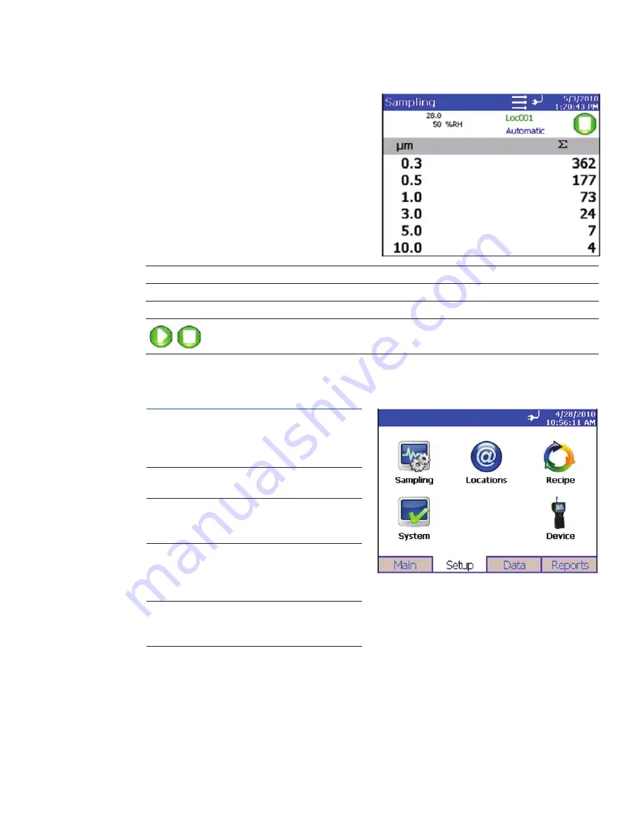
Zoomed Data Screen
The Zoomed Data screen is entered by touching in the size and count part of the main tab display. The bottom
portion of the screen summarizes the concentrations for the currently selected location. Tap the size and
count portion of the display to switch back to the Main Tab display.
The display shows:
• Temperature*
• Relative humidity*
• Air Velocity
• Bin sizes
• Particle count/concentration
Field
Description
Location
Label that displays information about the currently selected location.
Manual/Automatic/Beep
Mode Indicator; refers to the “Data Count Mode” (see section below).
Press the Start/Stop button to begin sampling in the confi gured mode.
Setup Tab
The setup tab provides access to the following:
Sampling
Setup
Set up Particle Channels, Sample Timing,
Particle Channel Alarms, Sample Count
Mode, Count Units, and Environment
display settings.
Locations
Setup
Identify and save the location informa-
tion associated with collected samples.
Recipe
Setup
Save a group of settings (a recipe) that
you use over and over so you don’t have
to reset individual settings.
System
Setup
Change Power On Password, Setup
Password, System Confi guration, Print
Settings, Print Schedule and Clear
Samples
Device
Setup
Set Date and Time, Screen Alignment,
Communications, Regional Settings, and
get device information.
Содержание APC ErgoTouch Pro 2
Страница 1: ...APC ErgoTouch Pro 2 Airborne Particle Counter Operation Manual...
Страница 34: ...34...
Страница 35: ...35...


