background image

OM-257220 Page 1

SECTION 1 − SAFETY PRECAUTIONS - READ BEFORE USING

som 2015−09

7

Protect yourself and others from injury —


read, follow, and save these important safety precautions and operating instructions.

1-1.

Symbol Usage

DANGER! − Indicates a hazardous situation which, if
not avoided, will result in death or serious injury. The
possible hazards are shown in the adjoining symbols
or explained in the text.

Indicates a hazardous situation which, if not avoided,
could result in death or serious injury. The possible
hazards are shown in the adjoining symbols or ex-
plained in the text.

NOTICE − Indicates statements not related to personal injury.

.

Indicates special instructions.

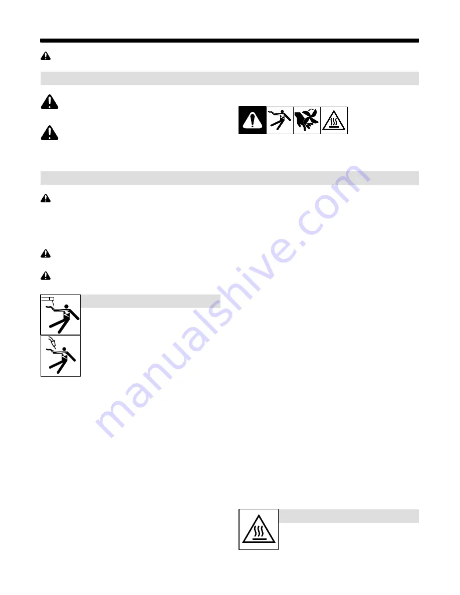
This group of symbols means Warning! Watch Out! ELECTRIC
SHOCK, MOVING PARTS, and HOT PARTS hazards. Consult sym-
bols and related instructions below for necessary actions to avoid the
hazards.

1-2.

Arc Welding Hazards

The symbols shown below are used throughout this manual
to call attention to and identify possible hazards. When you
see the symbol, watch out, and follow the related instructions
to avoid the hazard. The safety information given below is
only a summary of the more complete safety information
found in the Safety Standards listed in Section 1-5. 
Read and
follow all Safety Standards.

Only qualified persons should install, operate, maintain, and
repair this unit.

During operation, keep everybody, especially children, away.

Touching live electrical parts can cause fatal shocks
or  severe burns. The electrode and work circuit is
electrically live whenever the output is on. The input
power circuit and machine internal circuits are also
live when power is on. In semiautomatic or automatic
wire welding, the wire, wire reel, drive roll housing,
and all metal parts touching the welding wire are
electrically live. Incorrectly installed or improperly
grounded equipment is a hazard.

D

Do not touch live electrical parts.

ELECTRIC SHOCK can kill.

D

Wear dry, hole-free insulating gloves and body protection.

D

Insulate yourself from work and ground using dry insulating mats
or covers big enough to prevent any physical contact with the work
or ground.

D

Do not use AC output in damp areas, if movement is confined, or if
there is a danger of falling.

D

Use AC output ONLY if required for the welding process.

D

If AC output is required, use remote output control if present on
unit.

D

Additional safety precautions are required when any of the follow-
ing electrically hazardous conditions are present: in damp
locations or while wearing wet clothing; on metal structures such
as floors, gratings, or scaffolds; when in cramped positions such
as sitting, kneeling, or lying; or when there is a high risk of unavoid-
able or accidental contact with the workpiece or ground. For these
conditions, use the following equipment in order presented: 1) a
semiautomatic DC constant voltage (wire) welder, 2) a DC manual
(stick) welder, or 3) an AC welder with reduced open-circuit volt-
age. In most situations, use of a DC, constant voltage wire welder
is recommended. And, do not work alone!

D

Disconnect input power or stop engine before installing or
servicing this equipment. Lockout/tagout input power according to
OSHA 29 CFR 1910.147 (see Safety Standards).

D

Properly install, ground, and operate this equipment according to
its Owner’s Manual and national, state, and local codes.

D

Always verify the supply ground − check and be sure that input
power cord ground wire is properly connected to ground terminal in
disconnect box or that cord plug is connected to a properly
grounded receptacle outlet.

D

When making input connections, attach proper grounding conduc-
tor first − double-check connections.

D

Keep cords dry, free of oil and grease, and protected from hot metal
and sparks.

D

Frequently inspect input power cord and ground conductor for
damage or bare wiring – replace immediately if damaged – bare
wiring can kill.

D

Turn off all equipment when not in use.

D

Do not use worn, damaged, undersized, or repaired cables.

D

Do not drape cables over your body.

D

If earth grounding of the workpiece is required, ground it directly
with a separate cable.

D

Do not touch electrode if you are in contact with the work, ground,
or another electrode from a different machine.

D

Do not touch electrode holders connected to two welding ma-
chines at the same time since double open-circuit voltage will be
present.

D

Use only well-maintained equipment. Repair or replace damaged
parts at once. Maintain unit according to manual.

D

Wear a safety harness if working above floor level.

D

Keep all panels and covers securely in place.

D

Clamp work cable with good metal-to-metal contact to workpiece
or worktable as near the weld as practical.

D

Insulate work clamp when not connected to workpiece to prevent
contact with any metal object.

D

Do not connect more than one electrode or work cable to any
single weld output terminal. Disconnect cable for process not in
use.

D

Use GFCI protection when operating auxiliary equipment in damp
or wet locations.

SIGNIFICANT DC VOLTAGE exists in inverter weld-
ing power sources AFTER removal of input power.

D

Turn Off inverter, disconnect input power, and discharge input
capacitors according to instructions in Maintenance Section
before touching any parts.

HOT PARTS can burn.

D

Do not touch hot parts bare handed.

D

Allow cooling period before working on
equipment.

D

To handle hot parts, use proper tools and/or wear heavy, insu-
lated welding gloves and clothing to prevent burns.

Содержание 907525

Страница 1: ...ower Source XMT 450 CC CV OM 257220P 2016 10 Processes Description Multiprocess Welding File MULTIPROCESS R 400 Volt Model CE For product information Owner s Manual translations and more visit www Mil...

Страница 2: ...ntinue the tradition They re just as committed to providing equipment and service that meets the high standards of quality and value established in 1929 This Owner s Manual is designed to help you get...

Страница 3: ...IFICATIONS 13 4 1 Features And Benefits 13 4 2 Arc Controls 13 4 3 Serial Number And Rating Label Location 13 4 4 Unit Specifications 13 4 5 Dimensions and Weight 14 4 6 Environmental Specifications 1...

Страница 4: ...ION 9 SMAW CAC A OPERATION 38 9 1 Typical Connection For SMAW And CAC A Process 38 9 2 Remote Stick Welding Mode SMAW CAC A Process 39 9 3 Stick Welding Mode SMAW CAC A Process 40 9 4 Optional Low Ope...

Страница 5: ...V W AUX POWER CE 907525 Council Directives 2006 95 EC Low Voltage 2004 108 EC Electromagnetic Compatibility 2011 65 EU Restriction of the use of certain Hazardous Substances in electrical and electron...

Страница 6: ...il setting options welding programs are changed Occupational exposure is below the Exposure Limit Values ELVs YES NO for health effects at the standardized configurations if NO specific required minim...

Страница 7: ...neeling or lying or when there is a high risk of unavoid able or accidental contact with the workpiece or ground For these conditions use the following equipment in order presented 1 a semiautomaticDC...

Страница 8: ...ared according to AWS F4 1 and AWS A6 0 see Safety Standards D Do not weld where the atmosphere can contain flammable dust gas or liquid vapors such as gasoline D Connect work cable to the work as clo...

Страница 9: ...S can injure D Keep away from moving parts such as fans D Keep all doors panels covers and guards closed and securely in place D Have only qualified persons remove doors panels covers or guards for ma...

Страница 10: ...PA Standard 51B from National Fire Protection Association Quincy MA 02269 phone 1 800 344 3555 website www nfpa org OSHA Occupational Safety and Health Standards for General Indus try Title 29 Code of...

Страница 11: ...s dans un environnement humideou si l on porte des v tements mouill s sur des structures m talliquestelles que sols grilles ou chafaudages en position coinc e comme assise genoux ou couch e ou s il y...

Страница 12: ...br lures Le contact accidentel de l lectrode avec des objets m talliques peut provoquer des tincelles une explosion un sur chauffement ou un incendie Avant de commencer le soudage v rifier et s assur...

Страница 13: ...areil D Tenir l quipement c bles et cordons distance des v hicules mobiles lors de toute op ration en hauteur D Suivre les consignes du Manuel des applications pour l quation de levage NIOSH r vis e P...

Страница 14: ...ational Electrical Code NFPA Standard 70 from National Fire Protec tion Association Quincy MA 02269 phone 1 800 344 3555 website www nfpa org and www sparky org Safe Handling of Compressed Gases in Cy...

Страница 15: ...istributor for further information Safe37 2012 05 Wear dry insulating gloves Do not touch electrode with bare hand Do not wear wet or damaged gloves Safe2 2012 05 Protect yourself from electric shock...

Страница 16: ...rvicing unit Safe27 2012 05 Always wear long sleeves and button your collar when servicing unit Safe28 2012 05 After taking proper precautions as shown connect power to unit Safe29 2012 05 Do not use...

Страница 17: ...asd lk Kasjf laksf lkasdf l aksdf lkasd flksadflkasd lk Become trained and read the instructions before working on the machine or welding Safe40 2012 05 5min V V V Hazardous voltage remains on input c...

Страница 18: ...c Operation GTAW Remote Negative Inductance Foot Control Gas Metal Arc Welding GMAW U2 Conventional Load Voltage I2 Rated Welding Current Single Phase Increase Circuit Breaker Gas Tungsten Arc Welding...

Страница 19: ...perage at the start of a weld eliminating electrode sticking in CC and Stick Welding Modes see Sections 9 2 and 9 3 4 2 Arc Controls DIG control allows the arc characteristics soft versus stiff to be...

Страница 20: ...ty EMC This Class A equipment is not intended for use in residential locations where the electrical power is provided by the public low voltage supply system There can be potential difficulties in ens...

Страница 21: ...with China SJ T 11364 O 2 5 7 8 9 85 GB T26572 Indicates that the concentration of the Hazardous Substance in all homogeneous materials of the part is below the relevant threshold of China GB T 26572...

Страница 22: ...it overheats thermostat s opens output stops and cooling fan runs Wait fifteen minutes for unit to cool Reduce amperage or duty cycle before welding NOTICE Exceeding duty cycle can damage unit and voi...

Страница 23: ...tput capabilities of welding power source Curves of other set tings fall between curves shown AMPERAGE VOLTAGE CC Mode VOLTAGE CV MODE AMPERAGE 0 20 40 60 80 100 0 100 200 300 400 500 600 700 MAX MIN...

Страница 24: ...or CEC Section 20 1 Lifting Forks Extend forks beyond opposite side of unit 2 Lifting Handles Use handles to lift unit 3 Hand Cart Use cart or similar device to move unit 4 Line Disconnect Device Loc...

Страница 25: ...2x70 2x3 0 2x95 2x3 0 2x95 350 1 0 60 2 0 70 3 0 95 4 0 120 2x2 0 2x70 2x3 0 2x95 2x3 0 2x95 2x4 0 2x120 400 1 0 60 2 0 70 3 0 95 4 0 120 2x2 0 2x70 2x3 0 2x95 2x4 0 2x120 2x4 0 2x120 500 2 0 70 3 0...

Страница 26: ...f the weld cable terminal and copper bar are clean Tools Needed 3 4 in 19 mm 4 2 3 Do not place anything between Incorrect Installation 1 weld cable terminal and copper bar 5 5 Remote 14 Receptacle In...

Страница 27: ...Receptacle And Supplementary Protectors Ref 257348 B 1 115 V 7 Amp AC Receptacle 2 Supplementary Protector CB1 3 Supplementary Protector CB2 CB1 protects duplex receptacle CB2 protects 24 volts AC por...

Страница 28: ...ter to Gas In fitting Connect hose coupler to torch Connect one end of gas hose to hose coupler Connect remaining end of gas hose to Gas Out fitting Operation The gas solenoid controls gas flow during...

Страница 29: ...ceptacle or conductor rating to be less than the rating of the circuit protection device All components of the circuit must be physically compatible See NEC articles 210 21 630 11 and 630 12 50 60 Hz...

Страница 30: ...List is available at www MillerWelds com OM 257220 Page 24 5 9 Connecting Input Power Tools Needed 5 16 in 3 8 1 4 9 7 10 11 L1 L2 L3 GND PE Earth Ground 1 Input5 2013 04 Ref 803 766 C 257 348 A 2 4...

Страница 31: ...ine Install strain relief of proper size for unit and input conductors Route conductors cord through strain relief Tighten strain relief 3 Welding Power Source Grounding Terminal 4 Green Or Green Yell...

Страница 32: ...Sections 7 2 thru 9 3 1 Remote 14 Receptacle 2 Left Display 3 Right Display The meters display the actual weld output values after arc initiation and remains dis played for approximately three second...

Страница 33: ...anel Amps Lift Arc TIG GTAW Remote 14 Amps Panel Amps Scratch Start TIG GTAW Remote 14 Amps Panel Amps MIG GMAW Remote 14 Volts Volts Pulsed MIG GMAW P Remote 14 N A Arc Length 0 100 Stick SMAW CAC A...

Страница 34: ...ss 277777 A Turn off power before making con nections 1 Foot Control 2 Positive Weld Output Terminal 3 Remote 14 Receptacle Connect desired remote control to Remote 14 receptacle if required 4 Gas In...

Страница 35: ...to SCRATCH START TIG position as shown The open circuit voltage is shown in the Left Display Preset amperage is shown in the Right Display Operation The Adjust Control is used to set desired preset am...

Страница 36: ...Control is used to set desired preset amperage A remote control is required to turn on the weld output To start welding momentarily depress out put switch Touch tungsten electrode to workpiece at weld...

Страница 37: ...ode Switch to TIG position as shown The preset amperage is shown in the Right Display Operation The Adjust Control is used to set desired preset amperage A remote control is required to turn on the we...

Страница 38: ...ons 1 Remote 14 Receptacle 2 Positive Weld Output Terminal 3 Negative Weld Output Terminal 4 Ground Cable to Workpiece 5 Workpiece 6 Gun 7 Wire Feeder 8 Gas Hose 9 Gas Cylinder Use of shielding gas is...

Страница 39: ...lay Operation The Adjust Control is used to set desired preset voltage The preset voltage can be adjusted re motely at the wire feeder if the feeder has a voltage control This voltage con trol will ov...

Страница 40: ...ive Weld Output Terminal 4 Negative Weld Output Terminal 5 Ground Cable to Workpiece 6 Workpiece 7 Gun 8 Wire Feeder 9 Gas Hose 10 Gas Cylinder Use of shielding gas is dependant on Wire Type The conne...

Страница 41: ...itch 2 Left Display 3 Right Display 4 Adjust Control Setup For typical system connections refer to Section 8 3 Rotate Mode Switch to PULSED MIG posi tion as shown Left and Right Display will show PPP...

Страница 42: ...rminal 2 Negative Weld Output Terminal 3 Ground Cable to Workpiece 4 Workpiece 5 Voltage Sensing Clamp 6 Gun 7 Gun Trigger Receptacle 8 Wire Feeder 9 Gas Hose 10 Gas Cylinder Use of shielding gas is d...

Страница 43: ...tion as shown The Left Display toggles between open cir cuit voltage and preset voltage Operation The Adjust Control is used to set desired preset voltage The Left Display toggling momentarily pauses...

Страница 44: ...A Turn off power before making con nections 1 Electrode Holder Carbon Arc For CAC A process connect carbon arc cutting torch to to positive weld output ter minal 2 Electrode Holder 3 Positive Weld Ou...

Страница 45: ...rage When Configuration 3 is se lected remote control preset will be displayed in the amperage window See section 9 5 for more information regarding Alternate Configuration Functionality Adaptive Hot...

Страница 46: ...onfiguration 3 are ac tive remote controls will be ignored and amperagewill operate in panel only control See section 9 5 for more information re garding Alternate Configurations Adaptive Hot Start au...

Страница 47: ...es remote operation When configuration 2 is selected Stick mode operates in Panel Only control meaning any remote control that is plugged into the remote 14 control will be ignored and have no effect...

Страница 48: ...er before maintaining 3 Months Replace Damaged Or Unreadable Labels Replace Cracked Torch Body Repair Or Replace Cracked Cables Repair Or Replace Cracked Cables And Cords Clean And Tighten Weld Connec...

Страница 49: ...asure the DC voltage across the screw terminals on PC2 as shown until voltage drops to near 0 zero volts If the capacitor voltage does not drop to near zero after sev eral minutes use a bleeder re sis...

Страница 50: ...dicates a malfunction in the secondary power circuit of the unit If this display is shown contact a Factory Authorized Service Agent Help 25 Display Indicates machine has reached Duty Cycle limit See...

Страница 51: ...A complete Parts List is available at www MillerWelds com OM 257220 Page 45 Notes...

Страница 52: ...OM 257220 Page 46 SECTION 11 ELECTRICAL DIAGRAM Figure 11 1 Circuit Diagram...

Страница 53: ...OM 257220 Page 47 256 909 B...

Страница 54: ...Notes...

Страница 55: ...ns and Subarc SAW Torches Remote Controls and RFCS RJ45 Replacement Parts No labor Roughneck Guns Spoolmate Spoolguns Miller s True Blue Limited Warranty shall not apply to 1 Consumable components suc...

Страница 56: ...your personal records Always provide Model Name and Serial Style Number Contact a DISTRIBUTOR or SERVICE AGENCY near you Welding Supplies and Consumables Options and Accessories Personal Safety Equip...

Отзывы: