background image


34 

0x06 Write Single Register 

Request 


Communication address  1 byte 

0 to 255 

Function code 

1 byte 

0x06 

Register Address 

2 bytes 

0x0000 to 0xFFFF 

Register value 

2 bytes 

Value 

CRC 

2 bytes 

2 bytes CRC 

Response 


Communication address  1 byte 

1 to 255 

Function code 

1 byte 

0x06 

Register value 

2 bytes 

value 

CRC 

2 bytes 

2 bytes CRC 

Error 


Communication address  1 byte 

1 to 255 

Error code 

1 byte 

0x86 

Exception code 

1 bytes 

0x01 or 02 or 03 or 04 

CRC 

2 bytes 

2 bytes CRC 

*Note: communication address 0 is a broadcast command to 
the entire slave. The slave will not respond with a broadcast 
command. 


Содержание x20

Страница 1: ...user manual X20 EARTH FAULT RELAY...

Страница 2: ...2 EARTH FAULT RELAY Ver 1 00...

Страница 3: ...Measurement Menu 18 4 3 2 Records Menu 18 4 3 3 Configuration Menu 19 4 3 4 Protection G1 G2 Menu 22 4 3 5 Input Menu 23 4 3 6 Output Menu 25 4 3 7 Communication Menu 26 5 0 Password 27 6 0 Technical...

Страница 4: ...4 Appendix A IDMT Curves 45 Normal Inverse 45 Very Inverse 46 Normal Inverse 1 3 10 47 Long time Inverse 48 Extremely Inverse 49...

Страница 5: ...Records Settings and others The relay extends its connectivity by adopting the Modbus RTU protocol Through the use of RS485 standard protocol the user will be able to network the relay with other sla...

Страница 6: ...Acknowledge Acknowledg Alrm Alarm Alarm CT Current Transformer Current Tran Chg Change CLPU Cold Load Pickup DC Direct Current Dmnd Demand EF Earth Fault Gentrl General IDMT Inverse Definite Minimum...

Страница 7: ...7 7 1 2 Dimension of X20 96mm 96mm 125mm 105mm Front View Side View...

Страница 8: ...the following conditions Operating temperature 5 C to 55 C Humidity 56 days at 93 40 C non condensing Dust free environment away from electrical noise and radiation 2 1 Mounting a Insert the X20 thro...

Страница 9: ...slots on both sides of the X20 until the device is tightly secured on the switch gear panel The retainer clip can be removed by lifting the tab lightly at the handle end Retainer Clip Slide the retai...

Страница 10: ...10 c There are two methods to open door cover refer below Method 1 Open cover from right slot Method 2 Open cover from left slot...

Страница 11: ...ntact for tripping contact R2 7 Normally open contact for tripping contact R2 8 Normally close contact for tripping contact R2 9 Normally close contact for IRF contact 10 Normally open contact for IRF...

Страница 12: ...12 2 3 Wiring With 3 phase 4 wires...

Страница 13: ...13 13 With 3 phase 3 wires...

Страница 14: ...r and Esc are used to navigate through the menus and adjust the settings ESC To exit from menus submenus or to cancel setting value change Press and hold for 1 5 seconds to return to default display f...

Страница 15: ...through Earth Fault settings and to return to default display from any submenu if pressed and hold for 1 5 seconds Record To display Alarm records To display successive records press Record key again...

Страница 16: ...tus output status and measurement display for X20 These menus can be accessed by pressing ESC UP DOWN ENTER CLEAR and RECORD buttons 4 1 Main Page ILo 0 00 Up Down Output 1 2 0 0 Input 1 0 Date XX XX...

Страница 17: ...Down 4 PROTECTION G1 Up Down 5 PROTECTION G2 Up Down 6 INPUT Up Down 7 OUTPUT Up Down 8 COMMUNICATION Up Down Esc Enter Esc Enter Esc Enter Esc Enter Esc Enter Esc Enter Esc Enter Esc Enter Refer to 4...

Страница 18: ...ing which maximum and average values are stored Press Enter to change the value 4 3 2 Records Menu 4 3 2 1 Fault Records Whenever any trip fault happens in X20 information of trip value element source...

Страница 19: ...l value of the line frequency 4 3 2 2 CT Ratio Menu LCD Display Description E Gnd CT Pri Set the rated primary current of the Earth Ground CT Note The CT secondary should be connected to 5A CT input t...

Страница 20: ...nput One of the input functions must be set to Select Group if Input is selected Setting Group1 If above is set to Menu this will set the active protection group 4 3 2 5 Display Menu LCD Display Descr...

Страница 21: ...starting current like motor To use cold load pickup function one of the input function has to be set to Cold Load PU LCD Display Description CLPU Level Scaling value in percent for the cold load pick...

Страница 22: ...me delay type of Io tIo Set the value for the time delay of Io definite time if delay type of Io is set definite time Io IDMT Curve Set the type of curve if delay type of Io is set IDMT KtIo Set the t...

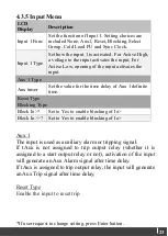
Страница 23: ...es the input Aux 1 Type Aux timer Set the value for the time delay of Aux 1 definite time Reset Type Blocking Type Block Io Set to Yes to enable blocking of Io Block Io Set to Yes to enable blocking o...

Страница 24: ...ted to select Protection Group 2 To enable changing group by input 3 4 Group Select Chg Group by must be set to Input Cold Load PU Activation of the input starts CLPU timer and increases protection th...

Страница 25: ...utput relay Remote Assign Remote trip to the output relay 4 3 6 2 Relay 2 Menu LCD Display Description Relay 2 Func Set the function of output Relay 2 Settings are included None Trip and Start Reset S...

Страница 26: ...er again and then number 0 at the column of output 2 will start blinking Press Up or Down to toggle the output contact 4 3 7 Communication Menu LCD Display Description Communication Set to Yes to enab...

Страница 27: ...s initiated The user enters each one of the 4 digits by using up or down key and validates each digit with Enter If Esc is pressed in between the password entering is terminated Password OK is shown i...

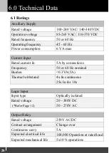
Страница 28: ...ted current In 5A by connections Frequency 50 or 60 Hz nominal Burden 0 3VA 5A Thermal withstand 4x In continuous 25x In for 10s Logic Input Input type Optically isolated Rated voltage 20 380V DC Refe...

Страница 29: ...Setting Ranges Earth Fault Io Yes or No Io 0 02 to 2 x In Io Delay type IDMT or Definite Time tIo 0 to 100s Io IDMT curve Normal Inverse Very Inverse Extremely Inverse Long time Inverse Normal Inverse...

Страница 30: ...s or No Remote set Yes or No Baud Rate 2400 4800 9600 19200 or 38400 Parity None Even or Odd Stop Bit 1 or 2 Relay Address 1 to 255 6 4 Measurement Range Measurement Range Earth Current Display 0 to 9...

Страница 31: ...is greater 6 6 Insulation Test IEC60255 5 Insulation Test High voltage dielectric withstand test 2kV rms 1 minute High voltage impulse test 5kV 1 2 50us 6 7 EMC Standard Test IEC60255 26 standard Test...

Страница 32: ...6 10Vrms 1kHz 80 AM 0 15 to 80MHz Radiated immunity IEC61000 4 3 10V m 80MHz to 1GHz 1kHz 80 AM Conducted emissions EN55011 Group 1 class B Radiated EM field emission CISPR 11 Group 1 class B 6 8 Env...

Страница 33: ...bytes 2 bytes CRC Response Communication address 1 byte 1 to 255 Function code 1 byte 0x03 0x04 Byte count 1 bytes 2 X N Register value N X 2 bytes Value CRC 2 bytes 2 bytes CRC Error Communication ad...

Страница 34: ...CRC Response Communication address 1 byte 1 to 255 Function code 1 byte 0x06 Register value 2 bytes value CRC 2 bytes 2 bytes CRC Error Communication address 1 byte 1 to 255 Error code 1 byte 0x86 Ex...

Страница 35: ...bytes Value CRC 2 bytes 2 bytes CRC Response Communication address 1 byte 1 to 255 Function code 1 byte 0x10 Quantity of Registers 2 bytes 0x0001 to 0x007b N CRC 2 bytes 2 bytes CRC Error Communicati...

Страница 36: ...d only Function 03h or 04h 0010 Relay status F2 Bit field Bit 0 15 0011 Relay LED status F3 Bit field Bit 0 3 0012 Input status F4 Bit field Bit 0 0013 Output status F5 Bit field Bit 0 2 0014 Active g...

Страница 37: ...or Average and Maximum Current F7 minute 1 60 0206 Year F7 year 0 199 2000 2199 0207 Month Day F10 month day 0 12 0 31 0208 Hour Minute F11 hour minute 0 23 0 59 0209 Miliseconds F7 ms 0 59999 020A Da...

Страница 38: ...ication Stop Bit F6 0 1bits 1 2bits 0214 Communication Address F7 1 255 0215 Password F7 0 0216 022F Reserved 0230 Cold Load Pickup Level F7 100 500 0231 Cold Load Pickup tCL F14 0 01s 10 60000 600s 0...

Страница 39: ...nt F18 Bit field Bit 0 10 0273 0274 Reserved 0275 Relay 2 Function F6 0 None 1 Start alarm 2 Trip 0276 Relay 2 Reset option F6 0 Manual 1 Auto 0277 Relay 2 Linked element F18 Bit field Bit 0 10 Protec...

Страница 40: ...Io F14 0 01 Ion 10 1000 10 0342 Earth Fault High Set tIo F14 0 01s 0 10000 100s Protection Group 2 Read Write Function 03h 04h 06h 10h 0400 0442 Same as Protection Group1 except addresses are 04xx in...

Страница 41: ...F7 0 1 as group 1 2 6 source threshold See below source threshold 0 12 0 10 7 Value high word 8 Value low word 9 14 Reserved 15 Io high word 16 Io low word Word number 6 High byte Fault record source...

Страница 42: ...is the register address of setting being changed 7 Io start 8 tIo trip If code is Group change 9 Io start 0 group 1 10 tIo trip 1 group 2 11 Remote trip 12 Remote acknowledge If code is output relay l...

Страница 43: ...tatus Bit 0 Output 1 0 off 1 on Bit 1 Output 2 0 off 1 on F6 Unsigned integer Miscellaneous 0 Group 1 1 Group 2 F7 Unsigned integer A numeric value of certain units Eg 12 may represent 12 or 12minutes...

Страница 44: ...ay represent 1 23A or 1 23s Refer to individual resisger s Units and Scale and range for detail F15 Unsigned integer Cold Load Pick up element Bit 0 2 Reserved Bit 3 tIo Bit 4 tIo Bit 5 Reserved F16 U...

Страница 45: ...45 45 Appendix A IDMT Curves Normal Inverse Appendix A...

Страница 46: ...46 Very Inverse...

Страница 47: ...47 47 Normal Inverse 1 3 10 1 0 0 9 0 8 0 7 0 6 0 5 0 4 0 3 0 2 0 1 0 05...

Страница 48: ...48 Long time Inverse...

Страница 49: ...49 49 Extremely Inverse...

Отзывы: