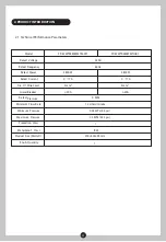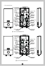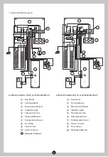
2.4 Internal Wire Diagram
6
WIRING DIAGRAM FOR FP-67WTR380WMTH-B1
WIRING DIAGRAM FOR FP-67WTR380WMTM-W1
⑧:
DC Pump
⑦:
Temperature Sensor
⑥:
Heating Elements
⑤:
Thermal Cut Out
④:
Indicator Light
③:
Main Control Board
②:
Terminal Block
①:
Key board
⑩:
Silicon Control
:Mutual inductor
11
⑨:
Flow Sensor
⑩:Mutual inductor
⑧:
Silicon Control
⑦:
Temperature Sensor
⑥:
Heating Elements
⑤:
Thermal Cut Out
④:
Indicator Light
③:
Main Control Board
②:
Terminal Block
①:
Key board
⑨:
Flow Sensor
L
N
CN6
5
6
4
7
9
1
2
N
PE
L
G
T1
T2
3
8
10
N
L
RL2
RL1
CN1
5
6
4
7
9
3
10
1
2
N
PE
L
G
T1
T2
8
11


