background image

REAR PANEL DESCRIPTION CONTINUED

Serial Port Secondary I/O: Analog input/output pinout shown below will provide status for remote

monitoring of the UPS.

Communication protection ports RJ11/RJ45: Protects against surges on a single phone, fax, modem or

Ethernet network lines. 

 EPO (Emergency Power Off) Port: The EPO port may be used to connect the UPS to a contact closure

 switch or control system to enable emergency shutdown (see page 16).

 Serial Port Primary: The serial port primary allows for communication with a PC (through RS232) or

 a control system. (Please Note: The USB and Serial ports cannot be used simultaneously)

Ground/Bonding Stud: Supplemental Bonding Point. Bonding of this point to the equipment and/or 

enclosure helps ensure optimum performance of the electronic system.

SERIAL PORT SECONDARY CONNECTOR PINOUT

15

16

17

19

20

12

13

13

Site Wiring Fault Input LED Indicator: This LED will illuminate to warn the user that a wiring problem 

exists within the AC mains electrical supply receptacle, such as reversed wiring. If illuminated,

disconnect all equipment and contact an electrician to ensure the outlet is properly wired

12

14

15

16

17

18

Page 8

Pin # 

Description

1

Indicates low battery condition.  If a low battery capacity condition occurs, pin 1 is (low), 

4

If pin 4 goes high (5V to 12V) for 10-15 seconds then a UPS shutdown will occur

5

Connect to ground (common) of control system I/O

7

+5VDC to +12VDC must be applied to pin 7 from control system I/O in order for 

communication to function 

8

Indicates utility power failure condition. If a power failure occurs pin 8 is (low) 

otherwise pin 8 is (high) 

14

21

18

otherwise pin 1 will be high 

(CONTINUED ON NEXT PAGE)

Expansion Port

E325394

6G48

Primary

Secondary

Serial Port

IN

OUT

125V

16A

60Hz

1650W

2150VA

Wiring Fault

Reset

EPO

D

A

T

A

Non-Critical Load

125VAC

60Hz - 16A

           Reset

  Non-Critical Load

           Reset

Critical Load

125VAC

60Hz - 16A

Input Circuit Breaker: Resettable circuit breaker provides input overload protection. 

Input:

48V

Содержание UPS-2200R-HH

Страница 1: ... 2200R HH UPS 2200R HHIP Rackmount UPS The UPS provides battery backup during power outages automatic voltage regulation during periods of inconsistent utility power and surge protection Please read this manual before removing the UPS from the shipping carton and before making any connections to and operating your UPS IMPORTANT UL R C US LISTED ...

Страница 2: ...iring Instructions 10 Installing Hardwired Input 11 Setup Of NIC UPS IPCARD 12 14 LCD Display Definitions 15 Battery Charging 16 Self Test 16 EPO Emergency Power Off Port Connection 16 Operation 17 General Status Mode 18 Functions Setup Mode 18 19 Battery Replacement 20 22 Optional External Battery Connection 22 Troubleshooting 23 24 Technical Specifications 25 26 Estimated Runtime 27 Warranty 27 ...

Страница 3: ...alert the user to the presence of uninsulated dangerous voltage within the product s enclosure that may be of sufficient magnitude to constitute a risk of electric shock WARNING Risk of battery explosion if battery is replaced by an incorrect type or rating WARNING To reduce the risk of fire connect only to a circuit provided with 20 amperes maximum branch overcurrent protection in accordance with...

Страница 4: ...Class A digital device pursuant to part 15 of the FCC Rules These limits are designed to provide reasonable protection against harmful interference when the equipment is operated in a commercial environment This equipment generates uses and can radiate radio frequency energy and if not installed and used in accordance with the instruction manual may cause harmful interference to radio communicatio...

Страница 5: ... MAY DAMAGE THE UNIT ALWAYS LIFT THE UPS BY HOLDING IT BY BOTH SIDES LIFT OUT OF BOX WHILE HOLDING BOTH SIDES OF UPS LIFT OUT OF BOX WHILE HOLDING BOTH SIDES OF UPS The UPS is very heavy and should be handled by two 2 people After the product is removed from its shipping carton inspect the UPS before installing and operating The shipping carton should contain the following items INSTALLATION AND M...

Страница 6: ...ears and the Rear Mounting Brackets are fully engaged slide to unit to the back of the enclosure 4 Install the front of the unit to the rackrail FIGURE C Two Person Installation 1 Determine mounting location 2 Properly support the unit from the bottom and carefully lift to the mounting location 3 While adequately supporting the bottom install the front of the unit to the rackrail FIGURE D 4 Instal...

Страница 7: ...it breaker Provides overload protection Expansion Port Slot for Network Interface Card NIC Part Number UPS IPCARD 6 5 9 10 USB Port Connects UPS to your computer via the supplied USB cable for UPS setup configuration and unattended shutdown in the event of a power failure For use with the supplied Middle Atlantic Power Manager software Please Note The USB and Serial ports cannot be used simultaneo...

Страница 8: ...will illuminate to warn the user that a wiring problem exists within the AC mains electrical supply receptacle such as reversed wiring If illuminated disconnect all equipment and contact an electrician to ensure the outlet is properly wired 12 14 15 16 17 18 Page 8 Pin Description 1 Indicates low battery condition If a low battery capacity condition occurs pin 1 is low 4 If pin 4 goes high 5V to 1...

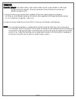
Страница 9: ...snap in connector 24 into the knock out until it is fully inserted See page 11 for hardwired input installation instructions 23 Snap in Connector Slide the connector into the knock out and secure in place Once the connector is inserted into the knock out it cannot be removed 20 19 22 23 Page 9 Expansion Port E325394 6G48 Primary Secondary Serial Port IN OUT 125V 16A 60Hz 1650W 2150VA Wiring Fault ...

Страница 10: ...lent Listed twist on connectors suitable for output conductor connections 2 Insert cable connector installer provided while guiding conductors to the J Box opening Slide on lock nut and and tighten on connector 4 Carefully place spliced conductors back into the J Box Reinstall J Box cover Page 10 WIRING INSTALLATION MUST BE PERFORMED BY QUALIFIED PERSONNEL UPS POWER MUST BE TURNED OFF AND MAINS PO...

Страница 11: ...ck out 3 Insert the snap in connector fully into the knock out There will be an audible click when the connector is fully inserted 2 Grab and hold the three conductors at the end of the hardwired input cord 23 Gently slide the flexible conduit until the snap in connector 24 meets the knock out on the UPS HOLD THE CONDUCTORS HERE Page 11 ...

Страница 12: ...he IP address for the Middle Atlantic Network Interface Card 1 Install the SNMP Card Configuration Tool from the included CD It is located on the CD in the tools network folder Double click the installation file MAP_SNMP_Setup msi to begin the installation 2 After the installation is complete run the Middle Atlantic UPS IPCARD Setup Utility program Under All Programs select Middle Atlantic Product...

Страница 13: ...Settings window as shown in FIGURE B The default IP Address is 192 168 20 177 the default Subnet Mask is 255 255 255 0 FIGURE B FIGURE C FIGURE D 6 Modify the IP subnet mask or gateway address Enter the new addresses into the corresponding fields 7 You will need to enter a password for the SNMP card in the authentication window as shown in FIGURE C Default user name admin Default password admin ad...

Страница 14: ...00 0C 15 00 00 01 then press Enter 3 Use the Ping command to assign a size of 123 bytes to the IP 1 Type in ping 192 168 20 240 1 123 then press Enter Method 3 Login from a Web Interface 1 Type the IP address of the UPS in your web browser and hit Enter to access the UPS There are two user account types Administrator default username admin default password admin Viewer default username guest defau...

Страница 15: ...rements of the UPS s internal battery and external battery Load Capacity Meter This meter displays the approximate output load level in 20 shaded increments of the UPS s AC outlets Silent Mode Icon This icon appears whenever the UPS is in silent mode The buzzer can be turned on or off by the user and does not beep during silent mode until the battery reaches low capacity Overload Icon This icon ap...

Страница 16: ... turned on press and hold the Select button for approximately 5 seconds until the UPS starts to beep Release the button 2 The Battery icon will appear on the LCD Display After approximately 10 or more seconds the UPS will revert back to normal mode EPO EMERGENCY POWER OFF PORT CONNECTION This feature is for those applications that require connection to an Emergency Power Off EPO circuit in case of...

Страница 17: ...l demands i e air conditioner refrigerator copier etc 2 Press the Power Switch to turn the UPS on The Power On Indicator will illuminate NOTE If an overload is detected an audible alarm will sound and the UPS will emit one long beep To correct this first turn the power off on a piece of equipment and unplug that piece of equipment from the UPS Wait approximately 10 seconds and reconnect the piece ...

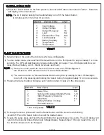
Страница 18: ... in Table 2 in the order given 4 To change functions press and hold the Select button until the six icons are blinking on and off Press the Select button to enter the desired value 5 To save the value press and hold the Select button for approximately 4 seconds The LCD display will return to the General Status Mode Input Voltage Display Repeat steps 1 through 4 each time any of the function values...

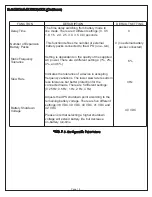
Страница 19: ...f the supplied AC power There are 4 different settings 1 2 4 and 6 6 Slew Rate Indicates the tolerance of a device in accepting frequency variations The lower slew rate results in less tolerance but better protection for the connected loads There are 5 different settings 0 25 Hz 0 5 Hz 1 Hz 2 Hz 4 Hz 4 Hz Battery Shutdown Voltage Adjusts the UPS shutdown point according to the remaining battery vo...

Страница 20: ...sk of short circuit current and electrical shock The following precautions should be observed before replacing the battery 1 Remove all watches rings or other metal objects 2 Only use tools with insulated handles 3 Do not lay tools or metal parts on top of battery or any terminals 4 Wear rubber gloves and boots 5 Determine if the battery is inadvertently grounded If inadvertently grounded remove t...

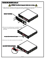
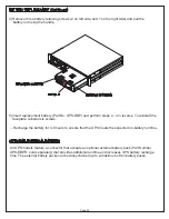
Страница 21: ...t Remove the right side of the panel to detach it from the unit 2 Remove the retaining screws securing the cable protection cover to the UPS and remove the cover 3 Disconnect the cable connectors from each other REMOVE FRONT PANEL DISCONNECT CABLE CONNECTORS Page 21 REMOVE CABLE PROTECTION COVER CAUTION The battery is heavy use caution when removing ...

Страница 22: ...stall six screws REMOVE 2 SCREWS REMOVE 1 SCREW HANDLE OPTIONAL EXTERNAL BATTERY All UPS models feature a connector that accepts an optional external battery pack Part Number UPS EBPR sold separately that provides additional runtime and increases UPS battery recharge time The external battery packs can be daisy chained up to a maximum of ten battery packs Page 22 Recharge the battery for 4 8 hours...

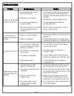
Страница 23: ...ected to an AC outlet 3 The battery is degraded 4 Mechanical problem 1 The serial cable or USB cable is not connected 2 The cable is connected to the wrong port 3 The unit is not providing battery power 4 The serial cable is not the cable that was provided with the unit 1 Recharge the battery by leaving the UPS plugged in 2 Contact Middle Atlantic Products about replacement batteries at 1 800 266 ...

Страница 24: ...PS and the UPS power is on If yellow LED is off Check if the network connection is valid 2 Check if the operated PC is on the same physical network as UPS Network Interface Card is 1 Use method 1 and method 2 to get correct IP address of the UPS Network Interface Card 2 If the operated PC is on the different physical network from the UPS Network Interface Card verify the setting of subnet mask and...

Страница 25: ...rotection Physical Output Receptacles Hardwired Output Dimensions in cm Weight Lb Kg Battery Sealed Maintenance Free Lead Acid Battery Hot Swappable External Battery 80 VAC 150 VAC 50 60 Hz 3 Hz auto sensing Pure Sine Wave at 120 VAC 7 50 60 Hz 1 4 ms On Utility Circuit Breaker On Battery Internal Current Limiting Yes RJ11 RJ45 One In One Out 1 Hardwired EKO 2 NEMA 5 20R 2U Rack 17 05 x 3 5 x18 9 ...

Страница 26: ... Battery Low Battery Overload Environmental Operating Temperature Operating Relative Humidity 32º F to 104º F 0º C to 40º C 0 to 95 Non Condensing Communication Power Manager Software Windows 98 ME NT 2000 XP Vista 7 Management Self Test Manual Self Test Auto Charger Auto Restart Yes COM Interface True RS232 x1 Analog I O x 1 Built in USB Interface Yes Page 26 ...

Страница 27: ...HE USE OF THE PRODUCTS PURCHASED EVEN IF THE COMPANY HAS BEEN ADVISED OF THE POSSIBILITY OF SUCH DAMAGES THE COMPANY S LIABILITY TO THE PURCHASER OR ANY OTHER PARTY HEREUNDER IF ANY SHALL IN NO EVENT EXCEED THE PURCHASE PRICE OF THE PRODUCTS PAID TO THE COMPANY Corporate Headquarters Corporate Voice 973 839 1011 Fax 973 839 1976 International Voice 1 973 839 8821 Fax 1 973 839 4982 middleatlantic ...

Отзывы: