

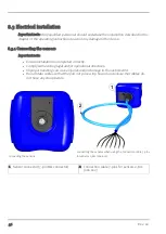


Chapter 8 Installation
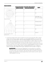
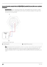
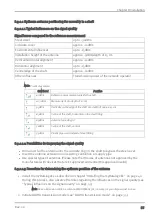
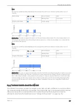
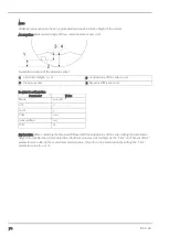
Schematic diagram of an universal input
If the universal input is operated in one of the analogue modes ("0-20 mA" or "4-20 mA"), switch
S1 is closed and the 1k resistance is thus bypassed.
Switch S1 is open when the digital modes ("Digital", "Cnt.Day" or "Cnt.Intervl.") are used.
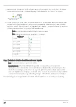
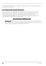
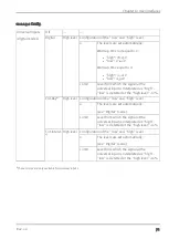
8.3.3.1 0/4...20mA mode
Resolution 6,10µA
I
max
25mA
Load
100
Ω
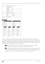
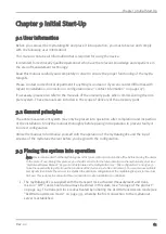
8.3.3.2 Digital modes (digital, day counter, pulse counter)
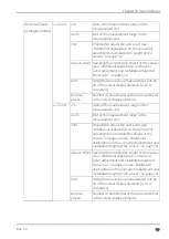
When using digital modes, the switching thresholds can be configured via the "High level"
parameter. The parameter is located in the "Config" tab of the "Measurement channels"
configuration section (see "Measurement channels" on page 67).
General
U
max
27,5V
Low
Configurable
High
Configurable
Load
1k1
Day and pulse
counter
Minimum pulse
length
20ms
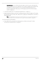
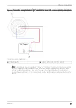
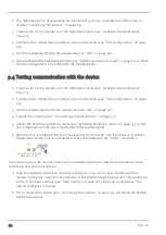
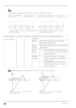
8.3.4 Technical details regarding the sensor supply
Schematic diagram of the sensor supply
Rev. 02
57
Содержание 305001
Страница 2: ......
Страница 8: ......
Страница 9: ...Chapter 2 Declaration of conformity Chapter 2 Declaration of conformity Rev 02 9 ...
Страница 10: ......
Страница 11: ...Chapter 3 Ex certification Chapter 3 Ex certification Rev 02 11 ...
Страница 12: ...12 Rev 02 ...
Страница 13: ...Chapter 3 Ex certification Rev 02 13 ...
Страница 14: ......
Страница 26: ......
Страница 38: ......
Страница 64: ......
Страница 84: ......
Страница 106: ......
Страница 108: ......
Страница 126: ......


