Microsemi Proprietary and Confidential. LX3301A/LX3302A Auto Calibration User Guide Revision 1.0
19
5
Data Capture Using IPCE with Microsemi Bench Control System
(BCS)
The following section describes how to use the Microsemi bench control system (BCS) to capture data.
5.1
Alternative Way to Take Data Using Dongle Programmer
The following instructions enable the programmer dongle to take measurements.
1. Configure IO2 as SENT.
2. Configure IO3 as DAC.
3. Enable debug by choosing ADC1.
4. Select
to write these parameters to EEPROM.
Write eeprom to chip
5. Read EEPROM to verify these parameters.
6. Select the Sensor measurement tab to view the measurements.
5.2
Collect Measurements with Default Parameters
At this moment in calibration, measurement data needs to be collected using default parameters. Run
the bench system and collect data simultaneously. You can choose to make your own measurements
through external test equipment. Depending on what type of data you want to collect (analog or digital),
you can use the Aout and Dout pins. For LX3302A, use IO3 as the Aout and IO2 as Dout. Data taken must
be in one of the two formats, as shown in the following image, to be compatible with the auto
calibration function. At least 18 measurements are required, no maximum limit.
Figure 34 • Data Formats
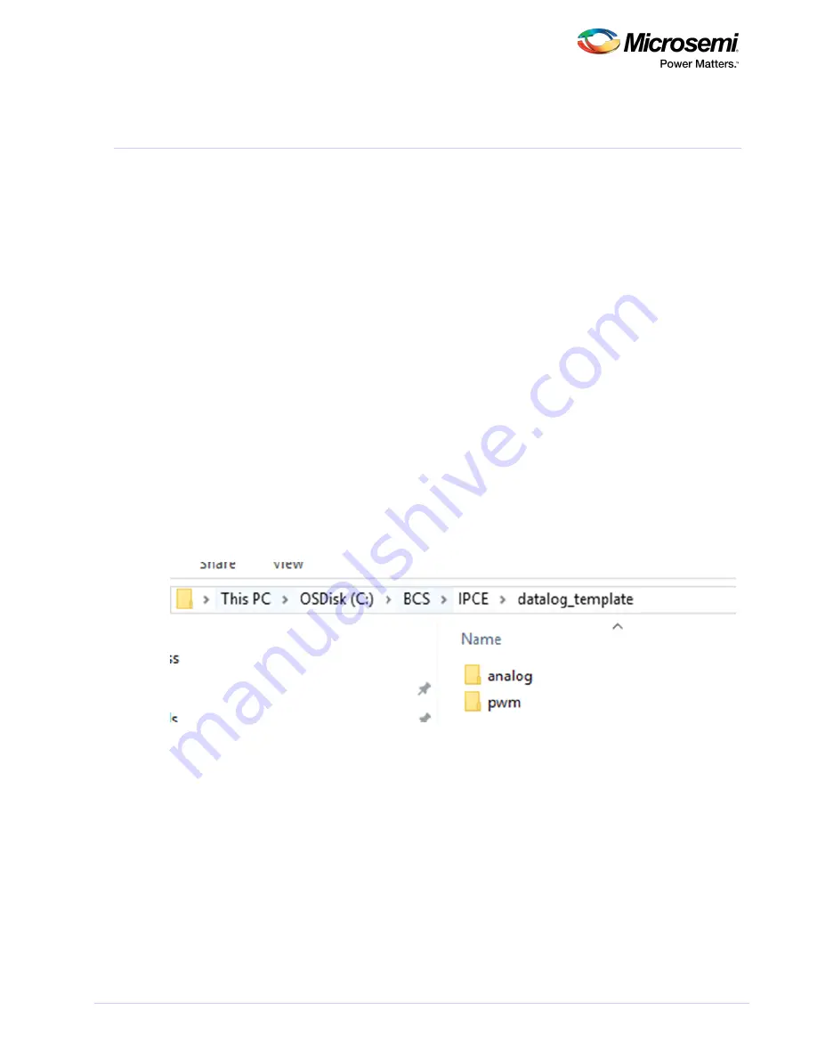
The following image shows how to set the calibration condition in the datalog file.


