


Rotary Microtome HM 325
MICROM International GmbH
Robert-Bosch-Str. 49
D- 69190 Walldorf
387821 - English
3-12
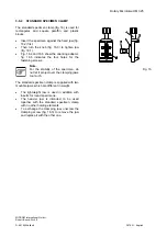
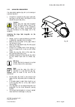
LARGE FIELD MAGNIFIER
The large field magnifier (fig. 26.1) is for looking at
section production.
•
The light is connected to the power outlet with
the power cord (fig. 26.2) and turned on and
off with the switch (fig. 26.3).
Caution:
Before using the large field magnifier
for the first time, please check if the
voltage conditions at the installation
site comply with the power requirements and
frequency mentioned on the supply unit of the
magnifier.
Installing the large field magnifier on the
microtome:
•
Please use the enclosed fastening elements
to attach the magnifier to the microtome.
•
Remove the cover plate on the upper side of
the instrument hood.
•
Remove the front plastic caps from the upper
side of the housing.
•
If there are no drilled holes in the housing, it
must be replaced with a new one with drilled
holes.
•
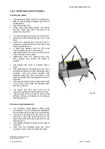
Fasten the peg (fig. 26.4) to the plate (fig.
26.6) with the screw (fig. 26.7).
•
Carefully introduce the four sleeves (fig. 26.8)
into the drilled holes with the screws (fig.
26.5).
Warning:
Please note that the sleeves do not fall
into the interior of the microtome!
Note:
Make sure the plate (fig. 26.6) is
mounted in a way that the peg (fig.
26.4) is closer to the front of the
microtome!
•
Put the plate (fig. 26.6) on the sleeves and
fasten it to the microtome with four screws (fig.
26.5).
•
A movable plastic socket that should be put
on the peg (fig. 26.4) is on the under side of
the magnifier.
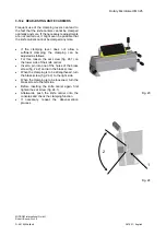
•
The magnifier can be adjusted forwards and
backwards for the most favorable viewing
position.
•
If the large field magnifier is not used, slightly
raise it and turn it sideways on the peg.
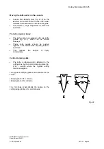
Fig. 26


