


Rotary Microtome HM 325
MICROM International GmbH
Robert-Bosch-Str. 49
D- 69190 Walldorf
387821 - English
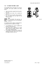
3-10-3 KNIFE CARRIER C
Inserting the knife:
•
To insert the knife, the clamping screws (fig.
21.3) must be unscrewed slightly so the knife
can be pushed in from the side.
•
The height of the knife is adjusted with the two
knurled nuts (fig. 21.6) and the bar (fig. 21.7).
•
If the cutting zone of the knife cannot be used
anymore, it can be moved over its entire
length to the left and right side by loosening
the clamping screws.
•
This allows an optimal use of the entire knife
edge.
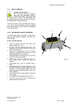
Caution:
When clamping the knife, please
tighten the two clamping screws (fig.
21.3) simultaneously.
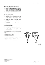
Clearance angle adjustment:
•
The clearance angle between cutting edge
and specimen can be shifted and adjusted to
the requirements of the tissue to be sectioned.
•
Loosen the clamping lever (fig. 21.4) on the
right side of the knife carrier and move the
upper part of the knife carrier (fig. 21.2) on the
base (fig. 21.1).
•
The adjusted clearance angle can be read on
the side scale.
•
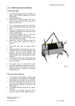
Then turn the clamping lever (fig. 21.4)
upwards to lock in the new clearance angle.
•
The clamping lever for the angle adjustment
can be pulled off after a correct angle setting
to avoid that the angle is "reset" unintendedly.
Note:
By experience, usable cuts are only
achieved at a clearance angle of 10° or
more.
•
If the clamping lever (fig. 21.4) is loosened,
the upper part of the knife carrier can be
moved 1 cm to the left or right side.
•
This way, the cutting edge can optimally be
used.
Fig. 21
1
2
3 4
5
6
7
8


