


2003 Microchip Technology Inc.
Preliminary
DS41206A-page 47
PIC16F716
7.4.5.1
Auto-Shutdown and Automatic
Restart
The auto-shutdown feature can be configured to allow
automatic restarts of the module following a shutdown
event. This is enabled by setting the PRSEN bit of the
PWM1CON register (PWM1CON<7>).
In Shutdown mode with PRSEN =
1
(PWM1CON <7>)
(Figure 7-15), the ECCPASE bit will remain set for as
long as the cause of the shutdown continues. When the
shutdown condition clears, the ECCPASE bit is
cleared. If PRSEN =
0
(Figure 7-16), once a shutdown
condition occurs, the ECCPASE bit will remain set until
it is cleared by firmware. Once ECCPASE is cleared,
the enhanced PWM will resume at the beginning of the
next PWM period.
The ECCPASE bit cannot be cleared as long as the
cause of the shutdown persists.
The Auto-shutdown mode can be forced by writing a '
1
'
to the ECCPASE bit.
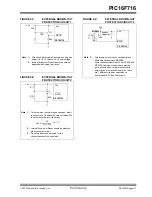
7.4.6
START-UP CONSIDERATIONS
When the ECCP module is used in the PWM mode, the
application hardware must use the proper external pull-
up and/or pull-down resistors on the PWM output pins.
When the microcontroller is released from Reset, all of
the I/O pins are in the high-impedance state. The
external circuits must keep the power switch devices in
the off state, until the microcontroller drives the I/O pins
with the proper signal levels, or activates the PWM
output(s).
The CCP1M1:CCP1M0 bits (CCP1CON<1:0>) allow
the user to choose whether the PWM output signals are
active-high or active-low for each pair of PWM output
pins (P1A/P1C and P1B/P1D). The PWM output
polarities must be selected before the PWM pins are
configured as outputs. Changing the polarity
configuration while the PWM pins are configured as
outputs is not recommended since it may result in
damage to the application circuits.
The P1A, P1B, P1C and P1D output latches may not
be in the proper states when the PWM module is
initialized. Enabling the PWM pins for output at the
same time as the ECCP module may cause damage to
the application circuit. The ECCP module must be
enabled in the proper Output mode and complete a full
PWM cycle before configuring the PWM pins as
outputs. The completion of a full PWM cycle is
indicated by the TMR2IF bit being set as the second
PWM period begins.
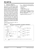
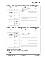
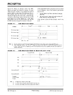
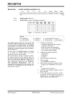
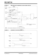
FIGURE 7-15:
PWM AUTO-SHUTDOWN (PRSEN =
1
, AUTO-RESTART ENABLED)
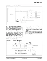
FIGURE 7-16:
PWM AUTO-SHUTDOWN (PRSEN =
0
, AUTO-RESTART DISABLED)
Note:
Writing to the ECCPASE bit is disabled
while a shutdown condition is active.
Shutdown
PWM
ECCPASE bit
Activity
Event
Shutdown
Event Occurs
Shutdown
Event Clears
PWM
Resumes
Normal PWM
Start of
PWM Period
PWM Period
Shutdown
PWM
ECCPASE bit
Activity
Event
Shutdown
Event Occurs
Shutdown
Event Clears
PWM
Resumes
Normal PWM
Start of
PWM Period
ECCPASE
Cleared by
Firmware
PWM Period
Содержание PIC16F716
Страница 6: ...PIC16F716 DS41206A page 4 Preliminary 2003 Microchip Technology Inc NOTES...
Страница 35: ......
Страница 56: ......
Страница 60: ......
Страница 88: ......
Страница 92: ...PIC16F716 DS41206A page 90 Preliminary 2003 Microchip Technology Inc NOTES...
Страница 108: ...PIC16F716 DS41206A page 106 Preliminary 2003 Microchip Technology Inc NOTES...
Страница 110: ...PIC16F716 DS41206A page 108 Preliminary 2003 Microchip Technology Inc NOTES...
Страница 124: ...PIC16F716 DS41206A page 122 Preliminary 2003 Microchip Technology Inc NOTES...


