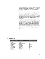
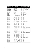
METRON PS-416M Скачать руководство пользователя страница 25


5-25

COMPONENT PART 

TYPE/VALUE 

QTY

DIAGRAM REFERENCE 


Resistor 

5K6  1%    0.5W 

R37, R39 

Resistor 

11K  1%    0.5W 

R42, R45,  R77, R78 

Resistor 

14K  1%    0.5W 

R5, R44, R26, R35 

Resistor 

15K8  0.50%  0.5W 

R20 

Resistor 

17K8  0.50%  0.5W 

R22 

Resistor 

18K    1%    0.5W 

R3 

Resistor 

20K    1%    0.5W 

R6 

Resistor 

23K7  0.50%  0.5W 

R24 

Resistor 

28K    1%    0.5W 

R43 

Resistor 

40K2  1%    0.5W 

R31, R33, R36 

Resistor 

47K5  1%    0.5W 

R2, R57 

Resistor 

53K6  1%    0.5W 

R55, R59 

Resistor 

61K9   1%    0.5W  

R30 

Resistor 

64K9   1%    0.5W 

R53, R61 

Resistor 

75K     1%    0.5W 

R38 

Resistor 

76K8   1%    0.5W 

R34 

Resistor 

80K6   1%    0.5W 

R25, R32, R40, R51 

Resistor 

97K6   1%    0.5W 

R27 

Resistor 

165K   1%    0.5W 

R41, R88 

Resistor 

10M     5%    0.5W 

R1 

Resistor nettv. 

47Kx 8         

RP1, RP2 

Potmeter 

1K0 1 turn  

P1, P2 

Potmeter 

1K   20 turn 

P5 

Potmeter 

10K      20 turn  

P4 

Potmeter 

100K     20 turn 

P3 

Cer. capacitor 

22pF   100V     

Cl, C20 

Multilay. cap. 

1n    100V  X7R 

C20, C24 

Multilay. cap. 

10nF   50V  X7R  

C26 

Multilay. cap. 

22nF   50V  X7R  

C21 
 

Multilay. cap. 

100nF  50V  X7R  

20 

C5, C6, C7, C8,  C9, C12, 
C25, C13, C14, C17, C18, 
C19, C22  

Tantalum cap. 

10

)

F     25V       

C3, C4, C10, C15, C16 

Electrolyte Capacitor 

100

)

F   16V   rad.  

Cll 

Transformer 

CAN1979A          

TR1 

Slide Switch 

4PDT MSS4200       

SW1, SW6, SW7, SW8 

Slide Switch 

4P3T MSS4300       

SW5 

Switch 

ET05J 1V3BE (on) off 
(on)  

2 SW2, 

SW3 

Switch 

15 501           

SW4 

Nut to Switch 

16.300.09        


Содержание PS-416M

Страница 1: ...1 1 PS 416M User Service Manual PATIENT SIMULATOR...

Страница 2: ...mited Warranty METRON warrants that the PS 416M Patient Simulator will substantially conform to published specifications and to the documentation provided that it is used for the purpose for which it...

Страница 3: ...nd Terminals 3 13 3 2 Use 3 14 4 CONTROL AND CALIBRATION 4 17 4 1 Required Equipment 4 17 4 2 Preparation 4 17 4 3 Function Testing 4 17 5 COMPONENT FUNCTIONS AND PARTS 5 21 5 1 Theory of Operation 5...

Страница 4: ...1 4 This page intentionally left blank...

Страница 5: ...ity representative authorized to process changes and revisions to publications make the pen changes or insert the revised pages ensure that obsolete pages are withdrawn and either disposed of immediat...

Страница 6: ...1 6 This page intentionally left blank...

Страница 7: ...ht ven tricular one paced and one fetal maternal ECG simulation 1 2 Specifications 1 ECG General Lead Configuration 12 lead simulation derived from one resistively divided analog signal RL RA LA LL V1...

Страница 8: ...ivity 5 or 40 V V mmHg Accuracy 1 full scale 1 mmHg Calibrated Rate 80 BPM 7 Dynamic Blood Pressure Selections Atmosphere 0 mmHg Arterial 120 80 mmHg Left Ventricle 20 0 mmHg Right Ventricle 25 0 mmHg...

Страница 9: ...Connectors High Level Standard phone jack Low level 10 AHA color coded standard safety banana con nectors with detachable banana to snap adapter Power 9 V alkaline battery or battery eliminator Case...

Страница 10: ...1 10 This page intentionally left blank...

Страница 11: ...a replacement The customer will not have to wait for a claim to be investigated by the supplier The customer should place a new purchase order to ensure delivery 4 When returning an instrument to MET...

Страница 12: ...2 12 This page intentionally left blank...

Страница 13: ...s Press the top of the key to increase the value Press the bottom of the key to decrease the value 3 Enter Pressing this stores newly specified waveform value set by the keys 4 High Level ECG Connecto...

Страница 14: ...lide switch situated at the bottom right hand corner of the panel The instrument should be switched off when not in use to save the battery A flashing display indicates low battery power 2 Battery Rep...

Страница 15: ...e sensitivity switch pVN mmHg must be set to match the input sen sitivity of the patient monitor either 5 or 40 pVN mmHg The wave form is selected and stored in the display Prewired cables P N 17440 a...

Страница 16: ...re supplied with the PS 416M P N 17023 Battery Eliminator METRON s AC Adapter plug in power supply transformer allows you to use the PS 416M anywhere a standard electrical outlet is available To attac...

Страница 17: ...n of 70mA 20mA 4 3 Function Testing 1 Turn the Power Switch on The LCD display will briefly show the soft ware version number before showing the active ECG function 03 Press the Key Switches beneath t...

Страница 18: ...e in position II To measure LL the Lead switch must be in position I Re quirement 1000 ohms 30 ohms 10 Repeat test 9 only this time with Base ohms in position 500 To measure LA the Lead switch must be...

Страница 19: ...ence current between TP10 and TP9 nom 0 62v lmV 19 Measure and note the voltage between LL and RA typ 100 V Set the display at 3 and press Enter Measure the voltage once more and adjust P4 until the d...

Страница 20: ...4 20 This page intentionally left blank...

Страница 21: ...5 2 Functions Description 1 Power Supply The unit is powered from either an internal 9 V battery or an external battery eliminator Diode D1 protects against a wrong polarization Power switch SW1 take...

Страница 22: ...ocessor in put E6 via resistor R88 If the power falls below the threshold internally in the processor the program in the processor will cause the display to flash 4 Temperature Output The temperature...

Страница 23: ...d from the rest of the equipment to separate several connected instruments galvanically Blood pressure data is transferred serially from the processor to voltage regulator IC5 a 12 bit D A converter T...

Страница 24: ...R46 R47 R48 Resistor 84R5 1 0 5W 1 R17 Resistor 93R1 1 0 5W 1 R79 Resistor 100R 1 0 5W 1 R29 Resistor 150R 1 0 5W 1 R85 Resistor 174R 1 0 5W 2 R50 R76 Resistor 200R 1 0 5W 1 R49 Resistor 249R 1 0 5W...

Страница 25: ...tor 80K6 1 0 5W 4 R25 R32 R40 R51 Resistor 97K6 1 0 5W 1 R27 Resistor 165K 1 0 5W 2 R41 R88 Resistor 10M 5 0 5W 1 R1 Resistor nettv 47Kx 8 2 RP1 RP2 Potmeter 1K0 1 turn 2 P1 P2 Potmeter 1K 20 turn 1 P...

Страница 26: ...57 42 2 IC socket 52 pin PLCC 48 109 41 1 Space bar Ritcho SRS4 4 0 4 Battery el cont S G9312 01 Female 1 J1 Test plug Male 1 J4 Test plug Female 1 J5 Phono socket LPV1120 01 black Female 1 J6 Header...

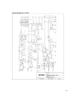
Страница 27: ...5 27 APPENDIX A DIAGRAMS Component Location Diagram Schematic Diagram Part 1 Schematic Diagram Part 2...

Страница 28: ...5 28 This page intentionally left blank...

Страница 29: ...5 29 Component Location...

Страница 30: ...5 30 Schematic Diagram Part 1...

Страница 31: ...5 31 Schematic Diagram Part 2...

Страница 32: ...5 32 This page intentionally left blank...

Страница 33: ...2 8500 Fax 1 616 454 3350 Fax 33 1 6078 6839 Fax 47 7391 7009 E mail metronus aol com E mail metronfrance infonie fr E mail support metron no From name Phone Address Fax Date PS 416M Error Report Prod...

Страница 34: ...5 34 This page intentionally left blank...

Страница 35: ...1 6078 8899 Phone 47 7382 8500 Fax 1 616 454 3350 Fax 33 1 6078 6839 Fax 47 7391 7009 E mail metronus aol com E mail metronfrance infonie fr E mail support metron no From name Phone Address Fax Date P...

Страница 36: ...5 36...

Отзывы: