


5-23
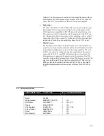
Output A7 on the processor is connected to the amplifier chain so that a
short impulse here will simulate a pace-impulse at the ECG output. Re-
sistors R36, R37, R38 and R39 set the level for the pace-impulse.
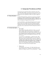
6.
Respiration
The other A/D channel in IC8 (Channel B) is used to generate the respi-
ration signal. This is generated according to the same principle as the
ECG signal, and is amplified in IC9. P2 adjusts the amplification in the
D/A converter, while P3 adjusts the rate of modulation at the ECG out-
put. The signal controls the resistance in two matching resistive optical
connectors. One of these is used for feedback, while the other simulates
respiration by modulating the output impedance for the ECG signal.
7.
Blood Pressure
The blood pressure output is isolated from the rest of the equipment to
separate several connected instruments galvanically. Blood pressure data
is transferred serially from the processor to voltage regulator IC5, a 12-
bit D/A converter. The interface has optical separation via the optical
connectors IC12, IC13, and IC14. Statistical values or waveforms for
blood pressure are generated from matrices in the processor. The D/A
converter is updated by new amplitude values 500 times per second. The
signal is amplified in IC16, and the level adjusted by P5. Slide switch
SW8 sets two fixed sensitivity levels at the output. The exciter signal
from the blood pressure meter is used as a reference for the D/A con-
verter.
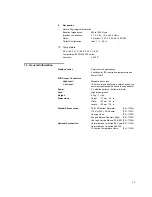
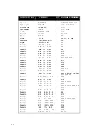
5.3
Component Parts
COMPONENT PART
TYPE/VALUE
QTY
.
DIAGRAM REFERENCE
Board AR-048 1
Microprocessor MC68HC711E9CFN
1
IC1
LCD-driver 74HC4543P 2
IC2,
1C3
Display NCno
SP530P
1
IC4
Volt. regulator
LP2951CN
2
IC5, 1C20
Volt. converter
MAX1044CPA
1
IC6
Timer ICM7555CN
1
IC7
D/A-converter AD7528JN
1
IC8
Содержание PS-416M
Страница 1: ...1 1 PS 416M User Service Manual PATIENT SIMULATOR...
Страница 4: ...1 4 This page intentionally left blank...
Страница 6: ...1 6 This page intentionally left blank...
Страница 10: ...1 10 This page intentionally left blank...
Страница 12: ...2 12 This page intentionally left blank...
Страница 20: ...4 20 This page intentionally left blank...
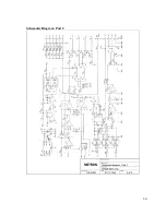
Страница 27: ...5 27 APPENDIX A DIAGRAMS Component Location Diagram Schematic Diagram Part 1 Schematic Diagram Part 2...
Страница 28: ...5 28 This page intentionally left blank...
Страница 29: ...5 29 Component Location...
Страница 30: ...5 30 Schematic Diagram Part 1...
Страница 31: ...5 31 Schematic Diagram Part 2...
Страница 32: ...5 32 This page intentionally left blank...
Страница 34: ...5 34 This page intentionally left blank...
Страница 36: ...5 36...


