


4-18
4. Connect the frequency meter to TP1 and read the frequency. Require-
ment: 2MHz
±
0.002MHz.
5. Connect the frequency meter to TP2 and read the frequency. Require-
ment: 100Hz
±
lHz.
6. Short circuit the 'Lead Test' terminals and check that the display is flash-
ing. Remove the short circuit.
7. Slowly reduce the voltage from the power supply until the display just
begins to flash. Measure the operating voltage with the multimeter. Re-
quirement: 6.2V
±
0.3V. Measure also the voltage between TP-13 and
TP-14. If the voltage is lower than 4.8V, adjust TR1 until the voltage is
4.8V. Turn the current up again to 9V.
8. Connect the oscilloscope to the High Level ECG contact and check that
there is a 80BPM ECG signal when function 03 is activated. The R-
impulse will have an amplitude of approximately 0.5V.
9. Set the power switch to Off. Measure the resistance from the RL output
to the RA, LA and LL outputs. To measure LA, the Lead switch must be
in position II. To measure LL, the Lead switch must be in position I. Re-
quirement: 1000 ohms
±
30 ohms.
10. Repeat test 9, only this time with Base-ohms in position 500. To measure
LA, the Lead switch must be in position II. To measure LL, the Lead
switch must be in position I.
Requirement: 500 ohms
±
15 ohms.
11. Measure the resistance from the V1 output to the V2,V3,V4,V5 and V6
outputs.
Requirement: 1000 ohms
±
30 ohms.
12. Measure the resistance between TP10 and TP14 with the multimeter.
Requirement: >10 Mohms.
13. Measure the resistance between the connections on the temperature con-
tact. The following table shows the required parameters:
TEMP 30
°
C
Min. - Max.
TEMP 37
°
C
Min. - Max.
TEMP 40
°
C
Min. - Max.
Pin4-Pin 1
1k8-1k83
1k34-1k37 1k19-1k21
Pin4-Pin 2
4k79-4k88
3k57-3k65 3k16-3k23
Pin4-Pin 3
24k0-24k5
18k0-18k4 16k0-16k3
14. Set the power switch in position while momentarily holding down
En-
ter
. The display will only show 0 in the right-hand column (the left col-
umn will be blank). PS-416M is now in
test/calibration mode. Connect a 10V
±
10mV voltage to J9 (the BP con-
tact), pins 3 and 5. Minus to pin 5. Check the voltage after connecting
the power.
Содержание PS-416M
Страница 1: ...1 1 PS 416M User Service Manual PATIENT SIMULATOR...
Страница 4: ...1 4 This page intentionally left blank...
Страница 6: ...1 6 This page intentionally left blank...
Страница 10: ...1 10 This page intentionally left blank...
Страница 12: ...2 12 This page intentionally left blank...
Страница 20: ...4 20 This page intentionally left blank...
Страница 27: ...5 27 APPENDIX A DIAGRAMS Component Location Diagram Schematic Diagram Part 1 Schematic Diagram Part 2...
Страница 28: ...5 28 This page intentionally left blank...
Страница 29: ...5 29 Component Location...
Страница 30: ...5 30 Schematic Diagram Part 1...
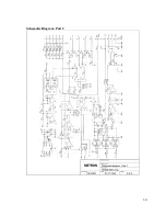
Страница 31: ...5 31 Schematic Diagram Part 2...
Страница 32: ...5 32 This page intentionally left blank...
Страница 34: ...5 34 This page intentionally left blank...
Страница 36: ...5 36...


