Installation Manual - Rev C
California Instruments
MX15 Series
16
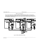
2.6.3 MX30/2 Output Wiring Diagram
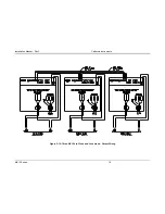
Figure 2-7 shows the required output connections for a MX30/2-1Pi or MX30/2-1Pi-MB output configuration (rear-view perspective).
Always disconnect all input power from the MX30/2 before removing the rear panel cover that provides access to the input and output
terminal connections. MX30/2 and MX45/3 systems are shipped with external output terminal blocks that enable the output wiring from
two or three chassis to be combined, providing a single point of connection to the EUT. These blocks are not enclosed however.
Figure 2-7: MX30/2 or MX30/2-MB Output Wiring
Содержание MX15
Страница 2: ......
Страница 3: ......
Страница 6: ...ii This page intentionally left blank ...
Страница 14: ...Installation Manual MX15 Series 10 Figure 2 3 MX15 AC Input Connection Diagram ...
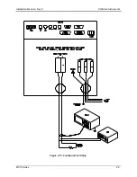
Страница 32: ...Installation Manual Rev C California Instruments MX15 Series 28 Figure 2 13 Functional Test Setup ...


