background image

Installation Manual - Rev C 


California Instruments 

MX15 Series 


24 

2.8  Multiple Cabinet System Configurations 

Multi-cabinet MX models consist of two or three autonomous or Auxiliary MX15-1Pi units. 
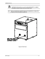
Auxiliary units do not have their own controller and are identified easily by their blank front panel.  
Master units each have their own controller but can be configured as auxiliary units by 
disconnecting the ribbon cable marked J17 between the controller and the system interface board 
(P/N 7005-701-1). This disables the controller and allows the MX15 to operate as an Auxiliary 
unit. (Requires removal of the top cover) 

When used as a multi-cabinet system for higher power applications, the controllers in the unit(s) 
acting as the auxiliary to the master are either disabled or not present.   

In addition to disabling the controller if present (as described above), the DIP switch (S1), located 
on the GPIB / RS232C / IO assembly in the auxiliary cabinets, settings need to be changed. 
(Requires removal of the top cover). The correct switch settings are shown below. (shown set for 
Master cabinet). Note that all units must be powered down before reconfiguring. Also, the output 
wiring must be changed to accommodate the new configuration. 

Note:  If the units being re-configured for multi-cabinet operation were not factory 

configured this way, it may be necessary to balance the amplifiers by adjusting 
their gain. Refer to MX15 Series User Manual (P/N 7005-960) for details on Amplifier 
balancing. 

When used as a multi-cabinet system, the system interface cables must be connected between 
the master and the auxiliary cabinets. 


Figure 2-12: Multi-Cabinet DIP Switch Location and Setting 

Top View from 
back of MX15 
Chassis 

Содержание MX15

Страница 1: ...phone 800 733 5427 toll free in North America 858 450 0085 direct Fax 858 458 0267 Email Domestic Sales domorders sd ametek com International Sales intlorders sd ametek com Customer Service service ppd ametek com Web www programmablepower com March 2011 Document No 7005 954 Rev C ...

Страница 2: ......

Страница 3: ......

Страница 4: ...Installation Manual AC Power Source California Instruments Models MX15 1 MX15 1Pi MX30 2 1Pi MX30 2 1Pi MB MX45 3 1Pi MX45 3 1Pi MB Rev C March 2011 ...

Страница 5: ...nly Notice of Copyright MX15 Series AC and DC Power Source Installation Manual 2010 AMETEK Programmable Power Inc All rights reserved Exclusion for Documentation UNLESS SPECIFICALLY AGREED TO IN WRITING AMETEK PROGRAMMABLE POWER INC AMETEK a MAKES NO WARRANTY AS TO THE ACCURACY SUFFICIENCY OR SUITABILITY OF ANY TECHNICAL OR OTHER INFORMATION PROVIDED IN ITS MANUALS OR OTHER DOCUMENTATION b ASSUMES...

Страница 6: ...ii This page intentionally left blank ...

Страница 7: ...onnel and equipment safety Always ensure that facility AC input power is de energized prior to connecting or disconnecting any cable In normal operation the operator does not have access to hazardous voltages within the chassis However depending on the user s application configuration HIGH VOLTAGES HAZARDOUS TO HUMAN SAFETY may be normally generated on the output terminals The customer user must e...

Страница 8: ...ctions of AMETEK is opened modified or disassembled in any way without AMETEK s consent or is used in combination with items articles or materials not authorized by AMETEK The Buyer may not assert any claim that the Products are not in conformity with any warranty until the Buyer has made all payments to AMETEK provided for in the Purchase Order Agreement PRODUCT RETURN PROCEDURE 1 Request a Retur...

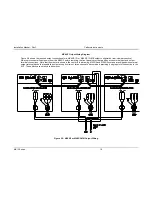
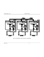
Страница 9: ...ction Diagram 10 Figure 2 4 Rear Panel 12 Figure 2 5 External sense cable shield connection to chassis ground 13 Figure 2 6 MX45 1 Output Wiring 15 Figure 2 7 MX30 2 or MX30 2 MB Output Wiring 16 Figure 2 8 Two MX15 s in Clock and Lock mode Output Wiring 17 Figure 2 9 MX45 3 or MX45 3 MB Output Wiring 18 Figure 2 10 Three MX15 s in Clock and Lock mode Output Wiring 19 Figure 2 11 Ship kit Terminal...

Страница 10: ... of order however P option Models with the Pi controller offer several additional standard features including the RS232C IEEE 488 interfaces arbitrary waveform generation and additional measurement functions The MX Series units are contained in a compact floor standing enclosure on casters This allows the units to be moved around more easily Read the installation instructions carefully before atte...

Страница 11: ...uate help when moving the unit Make sure the location floor in which the MX Series unit s will be installed can support the weight of the unit s 2 2 Power Requirements The MX Series power Source has been designed to operate from a three phase three wire Wye or Delta AC input line A protective earth connection is required as well PE Available three phase input settings are 208 VLL option 208 230 VL...

Страница 12: ...ilding wiring and other circuits from possible damage or shutdown in case of a system problem It will also facilitate removing AC input power to the MX system in case of service or reconfiguration requirements Note AC input wiring and connections must conform to local electrical safety codes that apply Always consult a qualified electrician prior to installation of any MX System AC input connectio...

Страница 13: ...r system using the ground stud located above the K1 relay Use a Green Yellow ground wire The mains source must have a current rating equal to or greater than the input fuses and the input wiring must be sized to satisfy the applicable electrical codes The front cover must be re installed prior to use and the strain relief provisions located at the rear bottom of the unit must be used to maintain p...

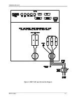
Страница 14: ...Installation Manual MX15 Series 10 Figure 2 3 MX15 AC Input Connection Diagram ...

Страница 15: ...a safe voltage before touching exposed pins of mains supply connectors Power modules need at least 15 Minutes to discharge to safe levels before they can be removed 2 5 AC On Off Circuit Breaker on MX15 front panel It is important to understand the purpose and operation of the On Off circuit breaker of the MX15 located on the upper left side of the front panel This is a 2A rated breaker that is us...

Страница 16: ... fuses can only be checked if the MX15 is completely de energized and disconnected from any AC power input Note Under no circumstances should AC input power be applied if one or more of the AC input line fuses have failed and opened up Figure 2 4 Rear Panel ...

Страница 17: ...minal block supplied is not of equal length Figure 2 5 External sense cable shield connection to chassis ground Note The output of the power source is isolated from the input line and floating with respect to chassis ground If needed either side HI or LO may be grounded If the EUT changes frequently you may want to consider using some quick disconnect scheme external to the MX15 so it will not be ...

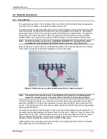
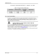
Страница 18: ...ble 2 2 The terminal block is located in the lower left corner on the rear of the unit The rear panel needs to be removed to access this terminal block CAUTION REMOVE ALL INPUT POWER TO THE MX15 BEFORE REMOVING THE REAR PANEL The correct standard size Allen wrench for connecting output wiring to TB1 is supplied with each MX15 in the ship kit Look for a brown envelope If the correct tools cannot be...

Страница 19: ...ng Diagram Figure 2 6 shows the required output connections for a MX15 1 or MX15 1Pi Always disconnect all input power from the MX15 before removing the rear panel cover that provides access to the input and output terminal connections Figure 2 6 MX15 1 Output Wiring ...

Страница 20: ...ways disconnect all input power from the MX30 2 before removing the rear panel cover that provides access to the input and output terminal connections MX30 2 and MX45 3 systems are shipped with external output terminal blocks that enable the output wiring from two or three chassis to be combined providing a single point of connection to the EUT These blocks are not enclosed however Figure 2 7 MX30...

Страница 21: ...Installation Manual Rev C California Instruments MX15 Series 17 Figure 2 8 Two MX15 s in Clock and Lock mode Output Wiring ...

Страница 22: ...om the MX45 3 before removing the front panel cover that provides access to the input and output terminal connections Note that the master is shown in the center in this drawing MX30 2 and MX45 3 systems are shipped with external output terminal blocks that enable the output wiring from two or three chassis to be combined providing a single point of connection to the EUT These blocks are not enclo...

Страница 23: ...Installation Manual Rev C California Instruments MX15 Series 19 Figure 2 10 Three MX15 s in Clock and Lock mode Output Wiring ...

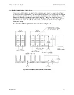
Страница 24: ...ed heavy duty terminal block One 2 position block is provided This block allows up to four wires to be combined into one larger wire gauge size wire The outputs of the 2 or 3 MX15 chassis are connected on one side of these blocks The EUT can be connected to the other side Note that the wire size to the EUT should be sized up to accommodate the double or triple currents per phase The dimensions of ...

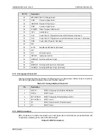
Страница 25: ...em Interface connectors P8 and P9 is located on the rear panel of each MX15 chassis The system interface is used to connect the multiple MX15 power sources in a Master Auxiliary configuration to create MX30 2 and MX45 3 models In these configurations only the Master MX15 power source has a built in controller and front panel Table 2 3 System Interface Connectors P8 P9 Description 1 OUTP Output ON ...

Страница 26: ...ror Signal Phase A high 35 N C 36 B ERR LO Error Signal Phase B low Not Used 37 C ERR HI Error Signal Phase C high Not Used 2 7 2 Analog Input Connector Input screw terminal strip Functions are called out on rear panel decal Table shows connections from left to right when standing at the rear of the MX cabinet Table 2 4 Analog Interface Connector Pin Description 1 RPV HI INPUT Analog input for Ext...

Страница 27: ...his output connected If you don t get an output trigger on this BNC use the Function Strobe BNC instead 3 Function Strobe TTL output Same signal connection as Trigger Output 4 Clock TTL output on Master TTL input on Auxiliary 5 Lock TTL output on Master TTL input on Auxiliary 2 7 4 External Sense Connector Table 2 6 External Sense Connector Pin Description 1 Phase A sense 2 N C 3 N C 4 Neutral sen...

Страница 28: ...ster are either disabled or not present In addition to disabling the controller if present as described above the DIP switch S1 located on the GPIB RS232C IO assembly in the auxiliary cabinets settings need to be changed Requires removal of the top cover The correct switch settings are shown below shown set for Master cabinet Note that all units must be powered down before reconfiguring Also the o...

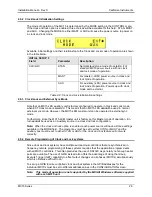
Страница 29: ...zed locked to the Master MX15 unit LKM This mode of operation requires that one MX15 have the LKM Lock Master option and one or two MX15 units have the LKS Lock auxiliary option 2 9 1 Clock Lock Configuration Settings Clock and lock configuration settings for LKM and LKS equipped MX15 s are set at the factory at the time of shipment and cannot be changed To check the configuration settings for an ...

Страница 30: ...c mode However the MX15 LKM master unit can be operated in external sync mode Furthermore since the MX15 LKM master unit is factory set for Master mode of operation it in turn cannot be used as an Auxiliary source in a clock and lock configuration Note When the clock and lock option is enabled each power source will have all three settings available in the MODE field The master box must be set to ...

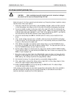
Страница 31: ... the auxiliary unit first and wait for them to cycle on then turn on the master unit 5 If the MX has more than one available output voltage range go to the PROGRAM screen move down to VRANGE and select the desired voltage range The output mode can be set from the PROGRAM screen as well Select AC mode 6 Set the output voltage to 0 volt and close the output relay with the OUTPUT ON OFF button There ...

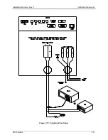
Страница 32: ...Installation Manual Rev C California Instruments MX15 Series 28 Figure 2 13 Functional Test Setup ...

Страница 33: ...Lock Initialization 27 Clock and Lock mode 26 Clock and Lock Mode Configuration 26 D DIP switch 25 E External Sync Clock Lock 27 F Functional Test 28 I installation 9 Introduction 7 M Multi cabinet 25 S sense wiring 14 V voltage drop cables 12 15 voltage rating 8 W Wire Sizes 12 15 wiring input 9 ...

Отзывы: