


Installation Manual - Rev C
California Instruments
MX15 Series
27
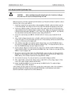
2.10 Basic Initial Functional Test
CAUTION:
Work carefully when performing these tests; hazardous voltages
are present on the input and output during this test.
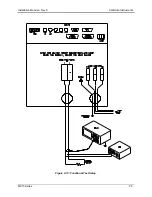
Refer to Figure 2-13 for the required functional test set up. Proceed as follows to perform a basic
function check of the power system:
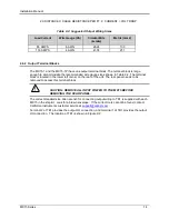
1. Verify the correct AC line input rating on the nameplate of the MX unit(s) and make sure the
correct three-phase line voltage is wired to the input of the MX before applying input power.
2. Connect a suitable resistive or other type load to the output of the MX. The load resistance
value will depend on the voltage range you plan to check. Make sure the power resistor has
sufficient power dissipation capability - up to 15 KW for full load test per MX15 - and that the
load used does not exceed the maximum power rating of the MX15.
3. Connect an oscilloscope and DMM / voltmeter to the AC source output. Set both for AC
mode.
4. If the correct voltage is present, turn on the MX unit(s) by closing the On/Off circuit breaker
on the front panel. For multi-cabinet systems, turn on the auxiliary unit first and wait for them
to cycle on, then turn on the master unit.
5. If the MX has more than one available output voltage range, go to the PROGRAM screen,
move down to VRANGE and select the desired voltage range. The output mode can be set
from the PROGRAM screen as well. Select AC mode.
6. Set the output voltage to 0 volt and close the output relay with the OUTPUT ON/OFF button.
There should be little or no output although the DMM may show a noise level, especially if the
DMM is in auto ranging mode.
7. Move the cursor to the VOLT field in the PROGRAM screen and either use the keyboard to
program a small voltage (20 VAC) or slew the voltage up slowly with the knob. Observe the
DMM reading. The reading should track the programmed voltage.
8. Also monitor the scope. The output should be a sinusoidal voltage waveform.
9. If the output tracks, increase the voltage until you reach 80 % of the voltage range or more.
Check the output voltage reading and waveform.
10. Select the MEASUREMENT screen by pressing the MEAS button. The output voltage,
current and power will be displayed.
In the unlikely event the power source does not pass the functional test, refer to the calibration
procedure in the MX15 Series User manual (P/N 7005-960) or ca
ll California Instrument’s
customer satisfaction department for further assistance.
Содержание MX15
Страница 2: ......
Страница 3: ......
Страница 6: ...ii This page intentionally left blank ...
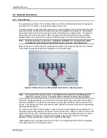
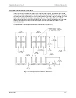
Страница 14: ...Installation Manual MX15 Series 10 Figure 2 3 MX15 AC Input Connection Diagram ...
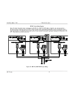
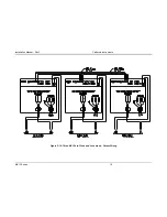
Страница 32: ...Installation Manual Rev C California Instruments MX15 Series 28 Figure 2 13 Functional Test Setup ...


