- 14
13. When you perform works where big forces are existing, the work piece should be additionally
protected through a block having an assembled roll or similar installation, which is to be
placed on the machine.
14. The machine capacity shall never be exceeded. For this purpose, check the" technical data"
on this rules and compare the values with the information given on the manufacture plate. All
the capacity information is based on a material having a resistance of 45 kg/mm
2
15. Should the hydraulic circuit flow be overloaded, the hydraulic oil will be led back to the reserve
tank over the overload valve until the pressure gets down again to the normal level.
Attention: HOWEVER, IT IS. NECESSARY TO UNDERLINE THAT IT MIGHT BE
DANGEROUS TO USE THE OVERLOAD VALVE AS A "SAFETY VALVE" IN ORDER TO
EXCEED THE MACHINE CAPACITY.
The producer presents all the instructions for a work protection and safety and hopes to have
a good and full calibration with you, the users, in order to ensure that the maximum Level of safety
could be obtained.
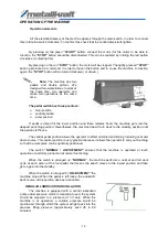
CONTROLS BEFORE PUTTING INTO OPERATION
1.
Press on the green " START " button in order to start the machine. In order to ensure this,
make sure that the red off button (" STOP") rotates clockwise (or directly to draw).
2.
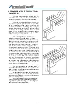
Make sure that the entries for hole stamp and cutting case are safety fixed.
3.
At the command table, change the status from "NORMA" to "ADJUSTMENT" ( Consider that
the readjustment course is not automatic at this position. When you leave the foot pedal
loose, the machine does not return to standby, rather it simply gets left).
4.
Make sure that the course limiter allows a maximum course. Now, press on the foot pedal so
often that the hole stamp stays in the cutting case. Take care that the hole stamp is regularly
arranged with the cutting case.
5.
Change the position from “ADJUSTMENT” to “NORMAL” at the command board. Now the
machine gets automatically back to the standby position.
6.
Check whether or not single cylinder perform, full course. Make sure that, no-hydraulic pres-
sure occurs at the and of related course. In order to ensure that there is no air available in the
hydraulic system, repeat the process several times (air might enter here during transport).
7.
Verify all tubes, hoses connections, branching and reserve tank for eventual hydraulic
leakage.
8.
Fix again all the protection parts and remove all loose subjects from the working zone of the
machine
The machine is now ready for your job.
Содержание HPS 115 DS
Страница 31: ...29 PUNCH TOOLS The part numbers in the above given figure 1belong to the standard equipment...
Страница 39: ...37 HYDRAULIC PLAN...
Страница 42: ...www metallkraft de...


