background image

E

D

R4 117

9 G2.16 10/03

11

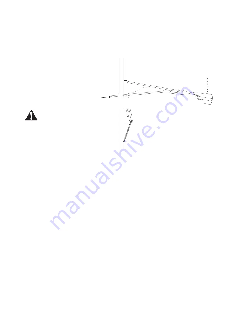
Additional setup for trackless tilt doors (jamb fittings) only

The aim of these steps is to make the opener push in the direction that the door edge is moving.
Preferably the door edge is being forced upward slightly as the closing cycle begins.
You must adjust the top limit of travel so that if you sight along the fully open door the sight line
intersects the pole in front of the trolley - not behind the trolley.
If the door does not open far enough after setting the top limit of travel correctly then it will be
necessary to make some in-
stallation changes. You will
need to try some or all of: rais-
ing the location of the header
bracket further, lowering the
power head further or increas-
ing the length of the door arm
further.

WARNING The door

is not safe for unsu-

pervised operation until the

force sensitivity has been be

set.

Opener position and open door po-

sition for trackless tilt door

Sight line intersects pole
in front of the trolley

Setting the force sensitivity

STEP 1:

 Remove the lamp cover by turning the catch on its underside. Remove the green  control

panel cover.

STEP 2:

 Identify the green and the red control knobs marked open-force and close-force.

Note: The opener can be set to either determine its own safe operating force level, or it can be set
to allow a deliberately greater amount of force to be applied to the door.

STEP 3: 

To set the force levels automatically, press the program button and turn the control knobs

fully anticlockwise. Ensure that the door is engaged to the opener. Then operate the opener to
move the door in a single unobstructed movement from one limit position to the other. If no ob-
struction was sensed during this cycle then the opener will save the settings to memory. Operate
the opener to move the door back to the original limit position. Again, if no obstruction is sensed,
the settings will be stored in memory.

STEP 4: 

To set the force levels at some higher level, rotate the control knob to some position

clockwise from the auto-setting point.

STEP 5:

 If a very light door is being operated, and if a very gentle closing force is required, then

set the option switch marked ‘Light door’ to the ON position. Note that on a heavier door this
option switch position may result in unintended detections of obstructions.

NOTE: 

To reset the adaptive and automatic force settings at any time, press the program button

once.

Содержание prolift 230T

Страница 1: ...EDR4 1179 G2 16 10 03 1...

Страница 2: ...release red handle on a rope such that it rests at a height of less than 1 8 m Install any fixed control wired or wireless within sight of the door but away from moving parts and at a height of more...

Страница 3: ...n doubt about whether the door is suitable for automation consult Merlin Tilt door clearances The opener has been designed to fit most existing doors The minimum installation clearance from the garage...

Страница 4: ...econds 60 seconds and 90 seconds For a 30 second delay autoclose short ON For a 60 second delay autoclose long ON For a 90 second delay both short and long ON NOTE Auto closing will only work if the b...

Страница 5: ...se the Chain on the smaller of the two sprockets STEP 5 Thread up the chain The threaded end of the torpedo should now be pointing back toward the power head Additional setup for trackless tilt doors...

Страница 6: ...d mark this maximum door height onto the header above the top edge of the door On tilt doors with tracks this maximum height might be as low as the top edge of the closed door If a sectional door tors...

Страница 7: ...ener Check that the door does not hit the pole when manually open ing and closing Allow a minimum of 25mm clearance between the top edge of the door and the bottom of the pole Attaching the return pul...

Страница 8: ...the straight arm is all that is required on tilting doors Usually the L arm is attached between the door and the straight arm for use with sectional doors You may have to shorten or re drill the door...

Страница 9: ...wire to the power head Connect the wire to the two terminals inside the wall control box Mount the box to the wall CAUTION Keep the push button cable at least 60mm clear of mains power cables if it i...

Страница 10: ...stay on continuously at the fully closed position The green LED will stay on continuously at the fully open position Identify the green operate button Ensure the door is engaged on the trolley STEP 3...

Страница 11: ...trol panel cover STEP 2 Identify the green and the red control knobs marked open force and close force Note The opener can be set to either determine its own safe operating force level or it can be se...

Страница 12: ...t s underside Remove the green control panel cover to expose the setup controls Identify the red learn button To learn a remote button to operate the opener Press the learn button for 1 2 seconds unti...

Страница 13: ...have several openers that operate from this master remote then all these openers will begin to flash their courtesy lamps Press the button on the master remote that would normally operate the opener...

Страница 14: ...t The high level of Infra Red light in bright sunlight may temporar ily prevent normal operation of the opener Switch off the power to the opener Run the pair of cables from each sensor back to the ac...

Страница 15: ...le and strapping Trolley speed depending on sprocket and load 75 to 135mm sec Rated force 770N Standard pole length 2750mm to suit chain supplied Standard assembled overall length pole length 400mm 31...

Страница 16: ...on Some features or accessories may not be available in certain markets or areas Please check with your distributor Merlin service centres New Zealand Auckland phone 09 415 4393 Phone toll free 0800 6...

Отзывы: