CHARGING SYSTEM - 4C - 23
90-816462 2-695
Drive Belt Tension
Adjustment
Alternator
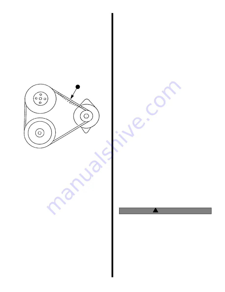
1. Install drive belt on pulleys and adjust tension as
follows:
a. Pivot alternator away from engine, as re-
quired, until correct tension is obtained as
shown. Belt should depress 1/2 in. (13 mm).
72669
a - Check Point
a
b. After obtaining correct tension, securely re-
tighten alternator brace attaching bolts and
alternator mounting bolts.
2. If a new drive belt has been installed, recheck belt
tension after running for five minutes.
Troubleshooting Tests
(Alternator on Engine)
Use the following tests in conjunction with the “Trou-
bleshooting” in Section 1. Before proceeding with the
tests, however, perform the following checks to elimi-
nate possible problem areas. Also observe “Precau-
tions,” preceding, to prevent damage to alternator
system.
1. If problem is an undercharged battery, check to
ensure that undercharged condition has not been
caused by excessive accessory current draw or
by accessories which have accidentally been left
on. Also, check that undercharged condition has
not been caused by running engine at too low a
speed for extended periods of time.
2. Check physical condition and state of charge of
battery, as outlined in “Battery - Storage” in Sec-
tion 4A. Battery MUST BE at least 75% (1.230
specific gravity) of fully charged to obtain valid re-
sults in the following tests. If not, charge battery
before testing system.
3. Inspect entire alternator system wiring for de-
fects. Check all connections for tightness and
cleanliness, particularly battery cable clamps and
battery terminals.
4. Check alternator drive belt for excessive wear,
cracks, fraying and glazed surfaces and replace
if necessary. Also, check drive belt tension and
adjust if necessary, as outlined under “Drive Belt
Tension Adjustment.”
Circuitry Test
Perform the following tests, using a 0-20 volt DC volt-
meter, to check that all of the circuits between the al-
ternator and the other components within the alterna-
tor system are in good condition.
!
WARNING
Be sure that engine compartment is well-venti-
lated and that there are no gasoline vapors pres-
ent (during the test) to prevent the possibility of
an explosion and/or a fire, should a spark occur.
ALTERNATOR OUTPUT TEST
1. Connect positive (+) voltmeter lead to alternator
output terminal (orange wire) and negative (–)
lead to a ground terminal on alternator. With en-
gine running about 1500 RPM and all accessories
turned on, voltage should be between 13.8-14.8.
Содержание 13
Страница 1: ...13 Printed in U S A 90 816462 2 695 1995 Brunswick Corporation GM 4 Cylinder MARINE ENGINES ...
Страница 2: ...90 816462 2 695 0 ...
Страница 7: ...1 A IMPORTANT INFORMATION GENERAL INFORMATION 72000 ...
Страница 15: ...1 B 50617 IMPORTANT INFORMATION MAINTENANCE ...
Страница 36: ...1 C IMPORTANT INFORMATION TROUBLESHOOTING ...
Страница 74: ...2 A 50633 REMOVAL AND INSTALLATION 4 CYL ALPHA ONE DRIVE ...
Страница 88: ...3 A 26790 ENGINE 181 CID 3 0L 4 CYLINDER GM ENGINE ...
Страница 137: ...4 A 72079 ELECTRICAL SYSTEMS STARTING SYSTEM ...
Страница 170: ...4 B 71855 ELECTRICAL SYSTEMS IGNITION SYSTEM ...
Страница 197: ...ELECTRICAL SYSTEMS CHARGING SYSTEM 4 C 72078 ...
Страница 237: ...4 D 72747 ELECTRICAL SYSTEMS INSTRUMENTATION ...
Страница 250: ...4 E 72938 ELECTRICAL SYSTEMS WIRING DIAGRAMS ...
Страница 264: ...5 A FUEL SYSTEM FUEL PUMP ...
Страница 271: ...5 B 72681 FUEL SYSTEM MERCARB 2 BARREL CARBURETOR ...
Страница 300: ...6 A 50628 COOLING SYSTEM SEAWATER COOLED MODELS ...
Страница 309: ...6 B 73665 COOLING SYSTEM CLOSED COOLING MODELS ...
Страница 325: ...C 6 EXHAUST SYSTEM MANIFOLD ...
Страница 331: ...7 A 71317 POWER STEERING PUMP ...


