


- 60 -
7-11.Sensor Arrangement
(1) Mount the XORG signal sensor for ORG-0, ORG-1, ORG-2 or ORG-3 and the XNORG/XORG signal sensor for ORG-10
on the -(CCW)LIMIT side along the work moving direction.
Example)
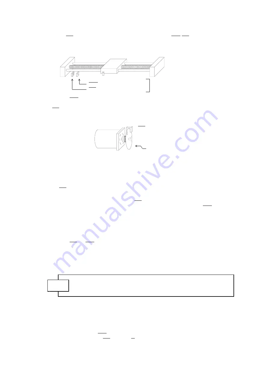
For a ball screw table
-(CCW)
Work
+(CW)
XNORG signal sensor for ORG-10
Use photo sensors.
XORG signal sensor
They shall turn off when light enters.
(2) ORG-4 and ORG-5
・Mount the XNORG signal sensor on the -(CCW)LIMIT side along the work moving direction in the same way
as (1).
・XORG signal sensor
When using a stepping motor:
Mount this sensor on the motor rotary shaft as shown below.
XORG signal sensor
MOTOR
Use a photo sensor.
It shall turn on when light enters.
Disc with slit mounted on the rotary shaft.
When using a servo motor:
Connect the encoder Z phase (Cφ) output sZ and -Z of the servo driver to the +XZORG and
-XZORG of the C-875.
For details, refer to Chapter 14.
The pulse width of the encoder Z phase (Cφ) output shall be 10μs or more.
(3) ORG-11,12
These types require the LIMIT sensor alone. XCCWLM signal is used as the origin signal.
Since XORG signal is also enabled, make sure that it will not be turned active.
7-12.Detecting Conditions
(1) For the ORG-0, ORG-1, ORG-2 and ORG-3 types, the XORG signal should be detected for 1ms or more when it
passes the ORG sensor at the maximum speed. For the ORG-4, ORG-5 and ORG-10 types, the XNORG signal
should be detected for 1ms or more when it passes the NORG sensor at the maximum speed.
(2) For the ORG-4 and ORG-5 types, the distance between point a and point b and the distance between point a
and point c should be N pulses or more in terms of the number of pulses.
*N=0.005×CSPD(Hz)
Example)
When CSPD=5KHz, N=0.005×5000=25.
(Minimum value of
Accordingly, the distance should be 25 pulses or more.
N is 1.)
Practically, give some allowance to it.
(3) Each of the XORG and XNORG signals should have no chattering.(When photo sensors are used, this does not
matter.)
(4) The distance between point a and +(CW)LIMIT shown in each process drawing should be enough for a slow stop.
(5) The distance between point a and point b shown in the ORG-10 type should be enough for a slow stop.
(6) With the ORG-11 and 12 detection, sufficient distance must be provided between the point a and the
machine limit in CCW direction so that slow stop (through deceleration) is ensured for the drive.
There may be a collision with the limit position of the mechanical device before stop.
CAUTION
his may lead to machine or workpiece damage.
Note that the stop point will be changed if RATE, HSPD, etc. are changed.
7-13.Other Functions
The following is additionally prepared as applied functions:
1.The ORIGIN DRIVE direction switch function for the time when you use the sensor in +(CW) side.
2.The MARGIN TIME function for preventing malfunction that can result from hunting.
3.The SENSOR TYPE select function used in the JOG DRIVE.
4.The ERROR DETECT function prepared for the time when the ORIGIN SENSOR detection ended unsuccessfully.
5.The function to produce XDRST signal as the origin detection is completed.
6.The function of ANDing the XORG signal and PO signal from the stepping motor driver.
For details of the applied functions, refer to the User's Manual [Applied Functions Part].
Содержание C-875
Страница 98: ... 98 2 M TYPE 3 H TYPE ...


