

12616, Rev. B
16. Replacement of Gear
47
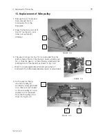
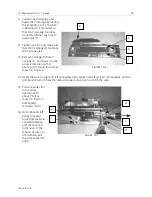
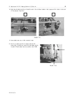
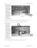
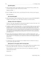
19. Remove work bolts and nuts,
set the cushion (T) to the side
bracket (S) in the arrow 1
direction as shown in Fig.16-
11,and set the bushing (U) in
the arrow 2 direction.
20. Connect the X-Y mechanism
to the baseplate (irrespective
of the relationship with the
needle) and turn on the
power supply.
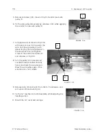
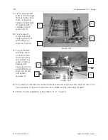
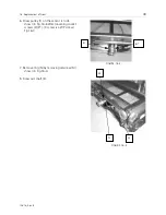
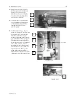
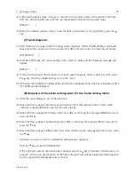
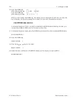
21. Continue pushing
key as
shown in Fig.16-12 to bring the
X-carriage (R) in the Y-sensor
direction until it no longer
moves, and make sure that the
gap (a) between the spring pin
2x16(W) and X-carrriage (R) is
more than 0.3mm. If the gap (a)
is less than 0.3mm, loosen
setscrews (B) of X-sensor, and
relocate the X-sensor leftward.
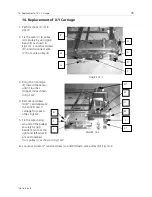
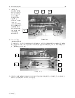
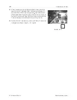
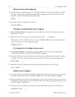
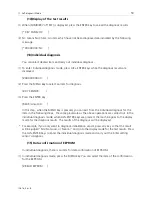
Fig.16-13. Push
key, and
make sure that the gap (a*)
between the side plate A and X-
carriage (R) is more than 0.3mm.
FIGURE 16-11
S
T
U
1
2
FIGURE 16-12
J
R
W
Y
0.3 mm
FIGURE 16-13
B