


32
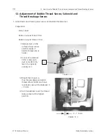
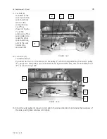
12. Adjustment of Bobbin Thread Sensor, Solenoid and Thread Breakage Sensor.
EP 1B Technical Manual
Melco Embroidery Systems
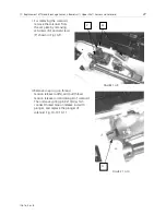
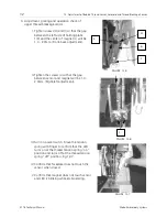
3. Adjustment, placing and operation check of
upper thread breakage sensor.
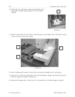
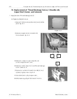
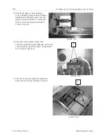
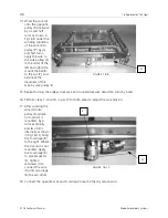
I. Tighten screws (H) and (I) so that the gap
between the left side of holding plate
1(K) and the center of magnet (L) will be
1.0 - 2.0mm. (Front-back adjustment).
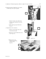
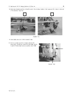
II.Tighten the screws (J) so that the gap
between sensor and magnet will be 1.0 -
2.0mm. (Right-left adjustment).
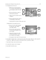
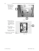
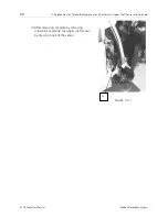
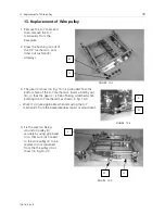
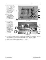
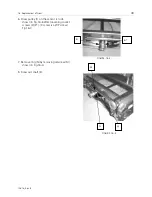
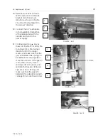
III. Turn on power switch. Move the tension
spring with finger to confirm that the LED
turns on at the thread tension spring "on"
position and turns off at the thread tension
spring "off" position. Fig.12-7.
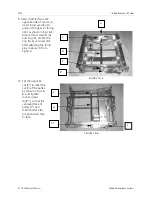
IV.Confirm that faceplate does not touch the
sensor when closed.
V.Confirm that magnet does not touch sensor
and LED is blinking while embroidering.
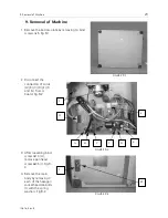
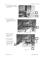
FIGURE 12-5
L
H
K
I
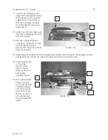
FIGURE 12-6
J
FIGURE 12-7