12616, Rev. B
16. Replacement of Gear
45
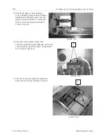
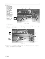
11. Put ball (R)
mounted at the
wire tip into the
spot-faced hole
which is the
same phase as
cut (P*) as
shown in Fig.16-
7. Set the
protrusion of the
wire holder (I) to
meet the other
spot-faced hole,
and fix the wire
holder (I) by
setscrew (M).
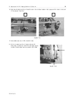
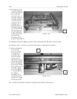
12. Turn wire (H)
counterclockwise
by six and half turns on the sensor (L) side pulley (F*) while closely attaching the wire to pulley
(F*), apply it to wire pulleys (E) in the order of the right and left sides, and mount ball(R) to cut
(P*) as shown in Fig.16-8.
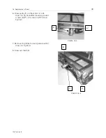
13. Bring the wire pulley (E) shown in Fig.16-8 in the arrow direction to eliminate the looseness of
the wire, and tighten setscrews (D) lightly.
FIGURE 16-7
R
I
M
P*
FIGURE 16-8
H
F*
E
D
L


