background image

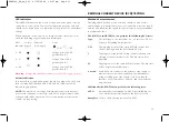
LED indicators

Three RED led indicators show circuit connection status when correctly
connected to a live circuit. These are for indication purposes only and
should not be relied upon as a indication of the presence of a hazardous
voltage. 

When connected to the circuit to be tested the three status LED’s will
show the following supply connection information:

LED Normal

Reversed 

Notes

Indicator Supply

(L-N) supply

=ON        = OFF

L - PE

Voltage between L- PE 
greater than 25 V

L - N

Voltage between L-N    
greater than 25 V

N - PE

Voltage between N-PE 
greater than 25 V

Warning:

Voltage indicator LED’s cannot reveal a N-PE supply reversal

Polarity Indication

If connected to a single phase power supply by a plug or by the 3-wire
lead set, three LED’s marked L-PE, N-PE and L-N respectively will
indicate supply polarity

NOTE:

The presence of a voltage between phase and earth does not

prove earth continuity, as the earth could have a high resistance and a
voltage would still be measured. To test earth continuity refers to the
sections on loop testing.

RESIDUAL CURRENT DEVICE [RCD] TESTING

11

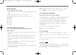
Method of measurement

The plug ended test lead or two wire lead should be used for this
measurement. A constant current source is connected across the supply
and the time taken for the supply to trip is measured by the instrument
in milliseconds (ms).

The RCDT310 and RCDT320 can perform the following RCD tests:

Type

The RCD type is selectable from, AC, AC Selective, DC, DC 
Selective, depending on instrument.

1/2I

Non-tripping test at half the rated RCD trip current for 2 
seconds, during which the RCD should not trip.

I

Tripping test at the rated RCD trip current started on zero 
crossing of the positive half cycle. The trip time will be 
displayed

5I

Tripping test at 5 x the rated RCD trip current. The trip time 
will be displayed in milliseconds.

0 or 180°

Some RCDs are sensitive to the polarity of the supply, i.e 
whether the test current is applied on the instantaneous 
rising or falling part of the supply cycle. Tests should 
therefore be performed at 0° and 180° and the maximum 
time recorded.

Additionally the RCDT320 can perform the following tests:

AUTO

Automatically steps through each RCD test (including 0 or 
180°) whilst the operator stands by the RCD to reset it.

RampTest

Used to check the trip current of an RCD.

RCDT300_UG_en_V01  07/05/2004  12:07 pm  Page 11

Содержание RCDT300 Series

Страница 1: ...M RCDT300 Series Residual Current Device testers USER MANUAL RCDT300_UG_en_V01 07 05 2004 12 07 pm Page 1...

Страница 2: ...ged Test leads probes and crocodile clips must be in good order clean and with no broken or cracked insulation The battery cover must be in place whilst conducting tests Voltage indicator LED s cannot...

Страница 3: ...the carton 5 LCD Display 6 Top panel 6 Lid open closure 17 Preparations for use 8 Batteries 8 Preliminary test lead check 8 General operating instructions 8 Display warning symbols 9 Setup procedure...

Страница 4: ...ent test RAMP 0 180 polarity selection Selective breakers INTRODUCTION GENERAL DESCRIPTION 4 Thank you for purchasing the Megger RCD Tester For your own safety and to get the maximum benefit from your...

Страница 5: ...RCDT320 1 x RCDT300 series RCD tester 1 x 3 wire test lead with prods with clips 8 x AA LR6 batteries fitted in instrument 1 x Test lead case 1 x Warranty card 1 x Calibration certificate 1 x Owners C...

Страница 6: ...0mA RCDT320 only 30mA 100mA 300mA 500mA 1000mA RCDT320 only Neck strap slots Test selector x I RCD trip time 1 x I RCD trip time 5 x I RCD trip time AUTO RCDT320 only Ramp RCDT320 only V AC DC volts R...

Страница 7: ...taining slot 4 Connection Panel RCDT300 Series test lead connections 7 Mains plug test lead connector Single or 3Phase connection Neutral or 2nd phase connection Warning Refer to User Guide Maximum 30...

Страница 8: ...ator will be displayed Default voltmeter The default voltmeter automatically operates in all test modes indicating connection to a live system Auto Power down To extend battery life the instrument wil...

Страница 9: ...ble on the instruments as per the relevant tables in the specification section of this document Reverse polarity detection Touch voltage setting To select Polarity reversal acceptance or rejection 1 W...

Страница 10: ...the TEST button to exit from the set up menu Test leads All test leads form part of the measuring circuit of the instrument and must not be modified or changed in any way or be used with any other ele...

Страница 11: ...ING 11 Method of measurement The plug ended test lead or two wire lead should be used for this measurement A constant current source is connected across the supply and the time taken for the supply to...

Страница 12: ...p 12 NOTE If the RCD should trip while performing a 1 2I test the error message trP will be displayed instead of the time display 1xI RCD trip time measurement To test the 1xI trip time of the install...

Страница 13: ...RCDs these should be tested at 0 and 180 or in the case of DC sensitive RCD s positive or negative Possible sources of error Measurement results can be affected by the following 1 Significant operatin...

Страница 14: ...a lower charge than Alkaline batteries and my not give much warning before becoming exhausted To replace batteries Warning Do not switch the instrument on with the battery cover removed 1 Switch off t...

Страница 15: ...hould not be left in an instrument which may remain unused for extended periods Fuse Blown indication The fuse blown symbol f indicates that an internal fuse has failed This instrument is fitted with...

Страница 16: ...indicates which Megger RCD300 series testers feature the Touch voltage inhibit feature RCD Testers Line reversal detection Inhibit available Y N Y N English language RCDT310 EN AU No No RCDT320 EN AU...

Страница 17: ...All units 980gms Dimensions All units 203 x 148 x 78 mm E M C In accordance with IEC61326 including amendment No 1 17 SPECIFICATION RCD Test Ranges to EN61557 6 Test Current Accuracy No Trip Test I 8...

Страница 18: ...y voltage temperature interference and system voltage and frequency where applicable 18 BASIC AND SERVICE ERRORS ACCESSORIES AND EQUIPMENT Item Order Code 2 wire test lead set and crocodile clips 6220...

Страница 19: ...Archcliffe Road Valley Forge Corporate Centre Dover 2621 Van Buren Avenue Kent CT17 9EN Norristown PA 19403 England U S A Tel 44 0 1304 502 243 Tel 1 610 676 8579 Fax 44 0 1304 207 342 Fax 1 610 676...

Страница 20: ...20 RCDT300_UG_en_V01 07 05 2004 12 07 pm Page 20...

Страница 21: ...21 RCDT300_UG_en_V01 07 05 2004 12 07 pm Page 21...

Страница 22: ...22 RCDT300_UG_en_V01 07 05 2004 12 07 pm Page 22...

Страница 23: ...23 RCDT300_UG_en_V01 07 05 2004 12 07 pm Page 23...

Страница 24: ...0 1 30 16 08 90 F 33 0 1 34 61 23 77 OTHER TECHNICAL SALES OFFICES Toronto CANADA Sydney AUSTRALIA Mumbai INDIA Madrid SPAIN and the Kingdom of BAHRAIN Megger products are distributed in 146 countrie...

Отзывы: