Fig.1
DET5/4
Features and controls
8
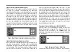
Fig.2 A method of connection where fault
conditions may occur
9
Fig.3 Low battery voltage indication
10
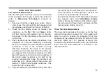
Fig.4 High Current spike resistance warning
11
Fig.5 Excessive ‘Noise’ warning
11
Fig.6 Reverse polarity indication
12
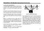
Fig.7 Fall-of-Potential method for measuring
resistance of an earth electrode
15
Fig.8 Fall-of-Potential method using single
lead to the earth electrode
16
Fig.9 Resistance areas associated with
electrode and Current spike
17
Fig.10 The 61,8% Rule method
17
Fig.11 Connection for Slope method
Fig.12 Resistance curve from Slope method
tests
19
Fig.13 Possible results from several Slope
method tests
20
Fig.14 ‘Dead’ earth testing
21
Fig.15 Test spike positions for BS7671
(16th Edition IEE Wiring Regulations
22
Fig.16 Determining ‘Touch’ potential
23
Fig.17 Determining ‘Step’ potential
24
Fig.18 Soil resistivity measurement
26
Fig.19 Resistivity calculation Nomogram
27
Fig.20 Continuity testing
28
Fig.21 Block diagram of instrument circuit
29
Fig.22 Instrument Accessories
34
Illustrations
4
DET 5/4R
Battery Charger Power cord
If the power cord plug is not suitable for your type of socket outlets, do not use an adaptor. You should use a
suitable alternative power cord, or if necessary change the plug by cutting the cord and fitting a suitable plug.
The colour code of the cord is:
Earth (Ground)
Yellow / Green
Neutral
Blue
Phase (Line)
Brown
If using a fused plug, a 3 Amp fuse to BS 1362 should be fitted.
Note: A plug severed from the power cord should be destroyed, as a plug with bare conductors is hazardous in
a live socket outlet.
Содержание DET5/4D
Страница 41: ...41...


