18
MEASURING TECHNIQUES Testing Earth Electrodes
For greater accuracy an average reading can be
calculated by moving the current spike, say 10 metres,
towards and then away from its first position and
making further resistance measurements. (Remember
that the Potential spike must also be moved in
accordance with the 61,8% Rule). The average of the
three readings can then be calculated.
THE SLOPE METHOD
This method is more applicable to larger earth
electrode systems or where the position of the centre of
the earthing system is not known or inaccessible (e.g.
if the system is beneath the floor of a building). The
Slope method can also be used if the area available for
siting the earth electrodes is restricted. It can be tried if
the previous methods prove unsatisfactory and
generally yields results of greater accuracy than those
methods.
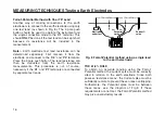
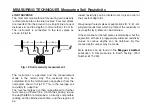
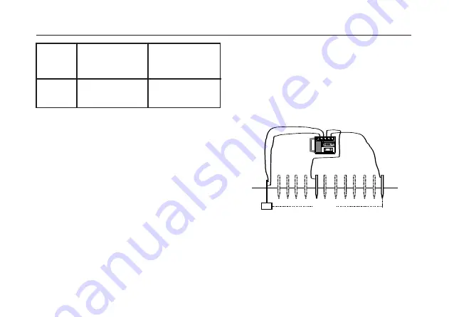
The equipment is set up as shown in Fig. 11. The
remote Current spike is placed 50 metres or more from
the earth electrode system to be measured and
connected to the instrument's 'C2' terminal. The
Potential spike is inserted at a number of positions
consecutively, between the earth system and the
Current spike, and connected to the 'P2' terminal. The
test spikes and the earth system should all be in a
straight line.
The instrument's 'C1' and 'P1' terminals are connected
separately to some point on the earth electrode
system.
Fig. 11 Connections for the Slope method
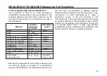
Distance to Potential
spike in metres from
centre of earth
system
Distance to Current
spike in metres from
centre of earth
system
Maximum
dimension
in metres
5
10
20
62
93
124
100
150
200
k
C1
P2
C2
ES
H
4 POLE
3 POLE
MEASURE RE
P1
ES
MEGGER
MEGGER
®
DET5/4D
DET5/4D
EARTH
EARTH
TESTER
TESTER
P1
C2
Electrode
under test
EC
P2
Содержание DET5/4D
Страница 41: ...41...


