15
FALL-OF-POTENTIAL METHOD
This is the basic method for measuring the resistance
of earth electrode systems. However, it may only be
practical on small, single earth electrodes because of
limitation on the size of area available to perform the
tests.
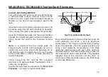
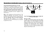
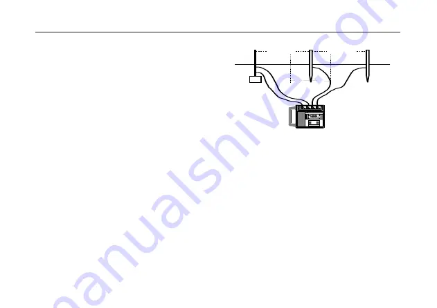
Insert the Current test spike into the ground some 30 to
50 metres away from the earth electrode to be tested.
Firmly connect this spike to the instrument terminal 'C2'.
Insert the Potential test spike into the ground midway
between the Current test spike and the earth electrode.
Firmly connect this spike to the instrument terminal
'P2'.
Note:- It is important that the Current spike, the
Potential spike and the earth electrode are all in a
straight line. Also when running the test leads out to
each remote spike, it is preferable not to lay the wires
close to each other in order to minimise the effect of
mutual inductance.
Firmly connect the 'C1' and the 'P1' instrument
terminals to the earth electrode. The diagram of Fig. 7
shows the connections.
Operate the instrument as explained in the 'Basic Test
Procedure', and note the resistance obtained.
Fig.7 Fall-of-Potential method.
Move the potential spike 3 metres further away from the
earth electrode and make a second resistance
measurement. Then move the potential spike 3 metres
nearer the electrode (than the original position) and
make a third resistance measurement. If the three
resistance readings agree with each other, within the
required accuracy, then their average may be taken as
the resistance to earth of the electrode. If the readings
disagree beyond the required accuracy then an
alternative method should be used e.g. the 61,8% Rule
or the Slope Method etc.
MEASURING TECHNIQUES Testing Earth Electrodes
3m
3m
15m to 25m
15m to 25m
Electrode
under test
Potential
spike
Current
spike
k
C1
P2
C2
ES
H
4 POLE
3 POLE
MEASURE R
E
P1
ES
MEGGER
MEGGER
®
DET5/4D
DET5/4D
EARTH
EARTH
TESTER
TESTER
Содержание DET5/4D
Страница 41: ...41...


