background image

Technical data (attachments)

Содержание AX 1000

Страница 1: ...X1000 MECALACBaumaschinenGmbH AmFriedrichsbrunnen2 D 24782B delsdorf Telefon 49 0 4331 351 325 Internet www mecalac de Telefax 49 0 4331 351 404 E Mail info mecalac de OPERATING INSTRUCTIONS ARTICULAT...

Страница 2: ...in as final customer and specify the FIN number truck identification number of your MECALAC truck When you already own an MECALAC truck you can also view the spare parts documentation here To do so p...

Страница 3: ...ns contain all the information which the user requires for operation and maintenance In the Maintenance section all maintenance work and operation tests are described which can be carried out bytraine...

Страница 4: ...P0860 P1000 P1010 I I Table of Contents Abbreviationsused UVV Unfallverh tungsvorschrift AccidentPreventionRegulations StVZO Stra enverkehrzulassungsordnung German Traffic Regulations Edition 01 2012...

Страница 5: ...e contractor or the contractor s authorized personnel 1 12 1 8 1 Organizational measures 1 12 1 8 2 Selection of personnel and necessary qualifications basic responsibilities 1 12 2 Signs 3 Protection...

Страница 6: ...ine or drive has failed 7 2 7 1 1 1 Towing the articulated loader when the engine has failed 7 2 7 1 1 2 Towing the articulated loader when the traction drive has failed 7 5 7 2 Lifting by crane 7 6 8...

Страница 7: ...AX 850 11 5 11 2 1 Loader 11 5 11 2 2 Engine 11 5 11 2 3 Starter 11 5 11 2 4 Alternator 11 5 11 2 5 Hydrostatic drive 11 5 11 2 6 Axle loads 11 5 11 2 7 Tyres 11 6 11 2 8 Steering system 11 6 11 2 9 B...

Страница 8: ...12 2 12 1 2 Fork lift attachment 12 4 12 1 3 Lifting hook 12 4 12 2 AX 850 attachments 12 6 12 2 1 Buckets 12 6 12 2 2 Fork lift attachment 12 8 12 2 3 Lifting hook 12 8 12 3 AX 1000 attachments 12 10...

Страница 9: ...Safety regulations...

Страница 10: ...other real values 1 2 2 Themachineandmanufacturer approvedattach ments may only be used in a technical non objectionable condition taking all safety regulations especially with regardtotheoperatingman...

Страница 11: ...pulled in 1 3 6 Allsafetyanddangerplatesonthemachinemust be observed 1 3 7 All safety and danger plates must be attached to the machine and must be kept in legible condition 1 3 8 In case of modificat...

Страница 12: ...ransported in a dedi cated passenger seat 1 5 1 2 Startanddrivethemachinefromthedriver sseat only 1 5 1 3 Observethecontrollampsaccordingtotheopera tion manual machine and engine during starting and s...

Страница 13: ...al behavior imme diately to the person in charge If necessary stop the machine immediately and safeguard it 1 5 1 15 Thedrivermayslewtheattachmentsinoverhead driving operatingandworkingareasonlyifthes...

Страница 14: ...prevent the machine from running or sliding down 1 5 1 27 Avoid such work which could have a detrimental effect on the stability of the machine The following may affect the stability overloading grou...

Страница 15: ...r the attachments must be guaranteed at all times during maintenance and repair work 1 5 2 5 Maintenanceandrepairworkmayonlybecarried out when the attachment is set down on the ground or supported or...

Страница 16: ...load over the heads of persons 1 5 2 16 In the case of erection work that must be carried out above normal human height suitable safety ascent devices and working platforms must be used Do not use en...

Страница 17: ...y use original fuses with stipulated ratings Immediately switch off the machine if the electrical supply fails 1 6 1 2 Whenworkingnearoverheadlinesandoverhead wires a safety clearance must be kept bet...

Страница 18: ...cable must be disconnected from the nega tive pole of the battery before inspection maintenance or repair of machine parts and components 1 6 1 7 Electric welding operations may only be per formed if...

Страница 19: ...ease 1 6 5 Gas dust steam smoke 1 6 5 1 The machine may be operated in closed rooms only if sufficient ventilation is ensured Ensure sufficient ventilation prior to starting the machine The regulation...

Страница 20: ...the use of such products 1 8 1 2 Inform yourself of the location use of fire extin guishers 1 4 arrow and first aid kit 1 8 1 3 When travelling on public roads a first aid kit a warning triangle and...

Страница 21: ...Signs...

Страница 22: ...last vorn zul Gesamtgewicht Betriebserlaubnis Nr 2 1 Baumaschinen GmbH D 24782 B delsdorf kg kg kg 12 18 17 11 20 19 20 27 3 CAUTION Steering only possible when engine is running 4 CAUTION The hydraul...

Страница 23: ...ign Maintenance schedule 15 Sign Tyre pressure 16 Symbol Stay out of the unprotected articulation area 17 Symbol Pilot valve for working hydraulics 4 8 4 Hand lever forward Lower bucket arm Hand lever...

Страница 24: ......

Страница 25: ...Protectionagainsttheft...

Страница 26: ...s well as details on the ROPS type the loader type and the permis sibleoverallweight 3 2 Parking the loader 1 Turn the steering wheel fully to the left or the right 2 Apply the parking brake 4 9 3 3 T...

Страница 27: ...d Advantages in case of an insured event The transponder for drive away interlock meets the new stricter requirements of the insurance companies Ask your insurance company for the appropriate details...

Страница 28: ......

Страница 29: ...Description...

Страница 30: ...protection 2 Bucket attachment 3 Pivot arm 4 Deflectionlever 5 Bucket arm 6 Tip cylinder in the bucket arm 7 Driver s cab 8 Hydraulic oil tank right loader side underneath the engine hood 9 Drive mot...

Страница 31: ...80 R18 15 5 55 R18 365 70 R18 405 70 R18 425 55 R17 For the running direction see Fig 4 2 NOTE Allfourtyresmustbeidenticalandhavethesame PRrating PR plyrating numberoftextileplies Steering system The...

Страница 32: ...issupportedby the hydrostatic traction drive inching i e during work the drive pedal is used for accelerating and braking Parking brake The parking brake is actuated with a hand lever 4 4 arrow locate...

Страница 33: ...e blocked until the damage is repaired The pipe break protection can be enabled or disabled 4 10 16 option Lifting device suspension option When the loader must be driven over larger distances especia...

Страница 34: ...ged so that they can be turned manually 10 Fit a suitable jack minimum capacity 3 0 tons from the side under the axle bridge in the vicinity of the axle fixture so that it is centred and cannot slip 4...

Страница 35: ...arking light Position II Road light 15 Toggle switch for windshield wiper washer rear Position I Wiper Position II Wiper washer pushbutton function 16 Pushbutton for releasing the quick change device...

Страница 36: ...nginefault Have an expert investigate the fault 13 Hydraulic oil filter clogging indicator opt 14 Signal lamp Hydraulic oil temperature 15 Air filter clogging indicator opt 16 Signal lamp Low cooling...

Страница 37: ...interval relay etc 4 14 are located behind the maintenance flap on the right side of the loader 4 13 arrow G1 Intervaltimer G2 Turnsignalrelay 1 Fuse controller engine 20 0 A 2 Maxi fuse power supply...

Страница 38: ...tendedmountingaidsorothersecure workingplatformswhenperformingworkabove reachingheight Donotuseanyloaderparts in particular attachments as climbing or descending aids Use safety harnesses when working...

Страница 39: ...ge that may be present and dismount the service plate 4 19 arrow or 4 20 2 NOTE Open the engine hood before opening the maintenanceflap 6 Loosen the screw 10 mm Allen key connecting the driver s cab l...

Страница 40: ...Unplug the hose leading to the compensation tank for coolant 4 22 2 from the adapter Pull electrical connector and hose as shown in Fig 4 22 upwards into the driver s cab upper section 9 Loosenthefas...

Страница 41: ...4 24 arrow 12 Attach 4 strand lifting gear into the crane lifting eyes 4 25 NOTE The two rear strands of the lifting gear must be approx 10 cm shorter than the front strands 13 Slowly lift the driver...

Страница 42: ...ntains eyecontactwiththeassignedhelpersanddecides on when and how they take action The operator of the crane for example makes sure no hazardous movements take place when helpers are in the danger are...

Страница 43: ...Operation...

Страница 44: ...6 1 clockwise to the stop 4 Insert the ignition key into the starter switch 4 8 7 and turn the key clockwise to position II 5 1 NOTE Indicators for battery charge parking brake engineoilpressureandpre...

Страница 45: ...eason starts Often they offer diesel fuel that can be used down to temperatures of 20 C super grade diesel fuel If the temperature is below 15 C or 20 C paraffin oil must be added to the diesel fuel F...

Страница 46: ...arryhisdriver slicense original and the operating permit original with him Beforedrivingonpublicroads thefollowingsafetymeasures must be taken 1 Lower the bucket arm until the lowest point of the buck...

Страница 47: ...us be reduced to 7 km h To attain full performance the combined action of propul sion and of the working hydraulics is necessary It is up to the operator to control the available power using the accel...

Страница 48: ...here are also four invariable air nozzles in the windshield area 5 8 arrows 5 2 5 2 Switching on the heater 1 Turn the knob 5 6 2 in the clockwise cold or the anti clockwise direction warm to reach th...

Страница 49: ...GER Ifparkingonagradientcannotbeavoided wheel chocks must be used and placed on the sloping sideofthefrontaxlewheelsinadditiontoapplying theparkingbrake andthearticulationsafeguard must be inserted On...

Страница 50: ...an be adjusted to the driver s weight with the hand wheel 5 9 3 4 Adjustorswingforwardthebackrestbysimultaneous ly pulling up the hand lever 5 9 4 5 4 2 Grammer seat 1 Weight adjustment Adjusttheseatt...

Страница 51: ...t their height To adjust the armrest height remove the round cap 5 13 arrow in the covering Loosen the hex nut wrench size 13 mm set the armrest asdesiredandtightenthenutagain Pushtheremovedcap onto t...

Страница 52: ...6 Longitudinaladjustment You can adjust the seat in longitudinal direction when you pull the lever 5 15 upwards NOTE The locking lever must engage in the desired position Itmustbeimpossibletomovethedr...

Страница 53: ...Attachments...

Страница 54: ...6 2 4 Lock the bucket with the pilot valve for the auxiliary hydraulics 4 8 5 5 Checkthatthedeviceismountedandlockedcorrectly on both sides DANGER Thetwoboltsofthequick changedevicemustbe in the bore...

Страница 55: ...ines at an equal distance from the centre 6 5 arrows and lock them Movingloadswiththefork liftattachmentisonly permitted close to the ground Protect the fork lift attachment against tipping over when...

Страница 56: ...ucket 6 9 2 andconnect them with the hoses of the quick change device 6 9 by tightly pushing them in CAUTION When making connections make sure that the hydraulic ports are clean and completely con nec...

Страница 57: ...ttachments DANGER 1 Only those attachments described in these operating instructions may be used 2 Weemphasisethatattachmentsthatarenot supplied by us are also not tested and approved by us Use of suc...

Страница 58: ......

Страница 59: ...Rescue towing lashing lifting by crane...

Страница 60: ...e rest of the hydraulic system 7 1 1 1 Towing the articulated loader when the engine has failed 1 Actuate the toggle switch for the hazard flasher 4 8 13 2 Set the drive switch 4 10 11 to 0 3 Apply th...

Страница 61: ...p bucket arm e g by inserting the bucket arm support option 1 2 arrow and lower bucket arm until it rests on the bucket arm support 9 Disable the float position by pulling the pilot valve for the work...

Страница 62: ...Theoperatoroftheloaderisresponsiblethatthe optional tool required to remove the mudguard items 12 and 13 and to adjust the drive pump item 14 is always on board the loader NOTE After towing has been c...

Страница 63: ...plug of the bucket protector into the socket 5 5 arrow option 6 Lift and mechanically prop up bucket arm e g by insertingthebucketarmsupport option 1 2 arrow and lowerbucketarmuntilitrestsonthebucket...

Страница 64: ...the longitudinal direction The max permissible load of the lashing load bearing points 7 6 arrows and 7 7 arrows is 2 0 t 7 2 Lifting by crane The loader to be lifted must be prepared as follows 1 Set...

Страница 65: ...avity C1 orC2 oftheloadersothat theliftingdeviceishorizontallyabovethelongi tudinal centre axis of the loader The lifting gear D must lead vertically upwards from the lifting points of the loader 7 6...

Страница 66: ......

Страница 67: ...Maintenance...

Страница 68: ...Designation Specification Viscosity Filling amount 1 Motor oil ACEA E7 E5 E3 API CI 4 acc to manufacturer ca 8 5 l with oil filter 2 2 Transmission oil MIL L 2105 B API GL5 6 LS SAE 85 W 90 LS approx...

Страница 69: ...e 4 9 3 andbysetting thedrivedirectionswitch 4 10 11 toposition 0 In addition wedges 8 1 2 must be placed on bothsidesofoneofthetwowheelsofthefrontaxle CAUTION Change the oil when the units are lukewa...

Страница 70: ...dge 8 3 arrow by carefully turning it back and forth 4 Clean the filter cartridge CAUTION For cleaning use a compressed air gun to whichapipe angledat90 hasbeenattached The pipe must be sufficiently l...

Страница 71: ...wo years Makesurethatnodirtordustcanenterthefilter housing during replacement of the safety cartridge 1 Remove the filter cartridge section 8 2 3 2 Pull out the safety cartridge 8 4 arrow by carefully...

Страница 72: ...il CAUTION Waste oil must be disposed of in such a way that it willnotcausepollution 3 Screw in the plug 8 7 1 again 4 Fillinoilviatheplugbore 8 7 2or8 8 arrow untilthe oil level reaches the opening N...

Страница 73: ...The oil level must reach the plug bore Collect any oil that escapes 2 Screw in the plug again 3 Unscrew the plug screw from the ancillary gear AX 700 20 km h and AX 850 20 km h 8 11 arrow or distribut...

Страница 74: ...he plug bore of the ancillary 8 14 1 or distribution gear 8 14 3 until the oil level reaches the opening NOTE The axle arch and the ancillary distribution gear do not have a common oil filling Details...

Страница 75: ...rew the drain plug and let the oil drain out CAUTION Waste oil must be disposed of in such a way that it will not cause pollution 4 Move the loader until the marking line OIL LEVEL is horizontal and t...

Страница 76: ...from mineral oil to biode gradable oil must be performed according to the VDMA 24 569 conversion guidelines CAUTION Theservicebrakemustbeoperatedwithmineral oil only 8 Check the oil level at the sight...

Страница 77: ...ge TheusedhydraulicoilfiltercartridgeandtheO ringsmustbedisposedofinanenvironmentally compatiblemanner 5 Fit the separator disc with a new O ring 8 22 4 6 Screw on the hydraulic filter lid with a new...

Страница 78: ...2 13 2 Bucket assembly CAUTION The bearing bolts grease nipples of the bucket assembly 8 26 through 8 30 must be greased every 10 operating hours 8 26 1 Bucket assembly front end 8 26 2 Front end lif...

Страница 79: ...0 Figure 8 29 8 28 arrow Tip cylinder deflection lever 8 29 1 Bucketassembly deflectionlever 8 29 2 Quick change device 8 29 3 Quick change device pivot arm 8 29 4 Deflectionlever pivotarm 8 30 1 Buck...

Страница 80: ...Figure 8 32 8 2 13 3 Driver s cab doors CAUTION The hinges of the doors of the driver s cabin 8 31 arrowsand 8 32 arrows mustbelubricated every 50 operating hours 8 2 13 4 Engine hood CAUTION The hin...

Страница 81: ...ion 7 It is located behind the maintenance flap at the loader right 1 Opening the window First pull the window handle inwards then push it outwards Finally lift the window handle out of its holder 2 O...

Страница 82: ...y 500 operating hours but at least every 1500 operating hours 6 Insert the filter element push the seat plate into the assembly position and secure again 8 2 17 Checking adjusting the service parking...

Страница 83: ...Faults causes and remedies...

Страница 84: ...oil Establish or clean connections according to electric wiring diagram Clean Check setting adjust if necessary Check whether electrical traction drive interruption is connected to brake lever Probab...

Страница 85: ...reinbasicmachine Replace fuse Carefully loosen the screwed connection on the end of the hose using the quick change couplings Oil squirts out and the increased pressure is eliminated Tighten the screw...

Страница 86: ......

Страница 87: ...Circuit diagrams...

Страница 88: ...ektrik Schaltplan Sch ma lectrique Wiring diagramm Elektrisch schakelschema El oversigt Elektriskdiagram Diagrama de conexiones el ctricas Elektrisk koblingsskjema El kopplingsschema Esquema de circui...

Страница 89: ...c circuit diagram Sheet item Designation 1 4 1 Multifunctionpanel 1 4 2 Actuator release of quick change device 1 4 3 Actuator rear window wiper washer 1 4 4 Actuator road lights 1 4 5 Actuator Hazard...

Страница 90: ...ht right 2 4 11 Fuse 15 0 A hazard flasher 2 4 12 Fuse 20 0 A windshieldwiper washer 2 4 13 Free 2 4 14 Fuse 20 0 A working light 2 4 15 Fuse 30 0 A beacon light 2 4 16 Maxi fuse 100 0 A 2 4 17 Maxi r...

Страница 91: ...g diagramm Elektrisch schakelschema El oversigt Elektriskdiagram Diagrama de conexiones el ctricas Elektrisk koblingsskjema El kopplingsschema Esquema de circuitos el ctricos S hk kytkent kaavio 2 3 4...

Страница 92: ...k Schaltplan Sch ma lectrique Wiring diagramm Elektrisch schakelschema Elektriskdiagram El oversigt Diagrama de conexiones el ctricas Elektrisk koblingsskjema El kopplingsschema Esquema de circuitos e...

Страница 93: ...Actuator Warning beacon opt 3 4 5 Actuator Permanent auxiliary hydraulics opt 3 4 6 Actuator Pipe break protection option 3 4 7 Actuator fan blower 3 4 8 Radio option 3 4 9 Relay for controller engine...

Страница 94: ...left 4 4 26 Reversing light right 4 4 27 Turn signal rear right 4 4 28 Tail light right 4 4 29 Brake light right 4 4 30 Tail light left 4 4 31 Brake light left 4 4 32 Dip pipe sensor 4 4 33 Switch Hy...

Страница 95: ...triskdiagram Diagrama de conexiones el ctricas Elektrisk koblingsskjema El kopplingsschema Esquema de circuitos el ctricos S hk kytkent kaavio 12 14 15 17 19 20 21 22 27 13 23 24 25 28 29 30 31 32 33...

Страница 96: ...rschaltung Klemme 15 Klimaanlage E Plan 3 4 11 Schalter Klimaanlage E Plan 3 4 11 Ventil L ftersteuerung E Plan 4 4 17 K hlmitteltemperaturschalter E Plan 4 4 18 Relais L ftersteuerung E Plan 2 4 22 S...

Страница 97: ......

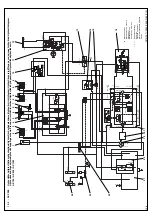
Страница 98: ...15 16 22 23 24 1 2 4 6 5 8 9 10 12 17 21 20 11 E E A M10x1 0 M14x1 5 M14x1 5 M10x1 10 muem B A 0 5 bar 125 muem 10 muem G1 2 G1 2 G1 2 A3 G1 2 B3 G1 2 A2 G1 2 B2 G1 2 A1 G1 2 B1 300 bar 270 bar G1 2 3...

Страница 99: ...X 850 High lift DW 100 45 600 895 AX 1000 DW 90 45 600 876 AX 1000 High lift DW 100 45 600 895 09 Pipe break protection lift cylinder option 10 lifting device suspension option 11 Steering unit 320 16...

Страница 100: ......

Страница 101: ...Technical data loader...

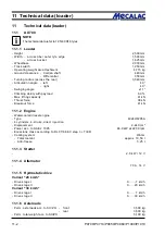
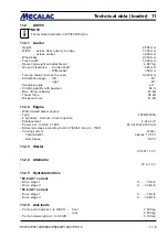
Страница 102: ...lity with payload 60 Max lifting capacity 41 kN Thrust force 38 kN Breakout force 41 kN 11 1 2 Engine Watercooled diesel engine Type 4024HF295A 4 cylinders 4 stroke direct injection Displacement 2 440...

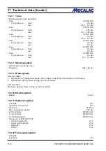
Страница 103: ...ng system Hydrostatic via priority valve Pressure max 180 bar 11 1 9 Brake system Service brakes 1 Hydraulic drum brake fast loader disc brake in the front axle acting on all 4 wheels 2 Hydrostatic in...

Страница 104: ...r Filter mesh 10 m abs Bypass response pressure p 2 5 bar 11 1 15 Combinationcooler AX 70 20 km h Performance max 31 12 kW Flow rate 89 26 l min AX 70 30 km h Performance max 35 15 kW Flow rate 89 26...

Страница 105: ...load 60 Max lifting capacity 43 kN Thrust force 38 kN Breakout force 41 kN 11 2 2 Engine Watercooled diesel engine Type 4024HF295A 4 cylinders 4 stroke direct injection Displacement 2 440 cm3 Power ac...

Страница 106: ...ng system Hydrostatic via priority valve Pressure max 180 bar 11 2 9 Brake system Service brakes 1 Hydraulic drum brake fast loader disc brake in the front axle acting on all 4 wheels 2 Hydrostatic in...

Страница 107: ...r Filter mesh 10 m abs Bypass response pressure p 2 5 bar 11 2 15 Combinationcooler AX 85 20 km h Performance max 31 12 kW Flow rate 89 26 l min AX 85 30 km h Performance max 35 15 kW Flow rate 89 26...

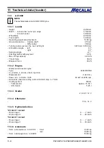
Страница 108: ...y with payload 60 Max lifting capacity 44 5 kN Thrust force 38 kN Breakout force 43 kN 11 3 2 Engine Watercooled diesel engine Type 4024HF295B 4 cylinders 4 stroke direct injection Displacement 2 440...

Страница 109: ...em Service brakes 1 Hydraulically operated disc brake at the front axle acting on all 4 wheels 2 Hydrostatic inching brake acting on all four wheels Parking brake Mechanic parking brake acting on all...

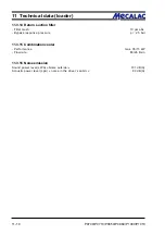
Страница 110: ...turn suction filter Filter mesh 10 m abs Bypass response pressure p 2 5 bar 11 3 15 Combinationcooler Performance max 35 15 kW Flow rate 89 26 l min 11 3 16 Noiseemission Sound power level LWA Noise o...

Страница 111: ...Technical data attachments...

Страница 112: ...P0700 P0710 P0850 P0860 P1000 P1010 12 2 12 Technical data attachments L A H6 G H8 HH12 HH13 H10 B L6 A 2 D J 12 1 AX 700 attachments NOTE The technical data refer to 12 5 18 tyres 12 1 1 Buckets...

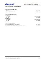
Страница 113: ...A2 Max dump angle top 46 45 Max dump angle bottom 125 125 B Max dumping distance at dumping angle 45 mm 1555 1545 G Dumping height at max dumping distance and dumping angle 45 mm 715 705 H6 Depth of...

Страница 114: ...P0700 P0710 P0850 P0860 P1000 P1010 12 4 12 Technical data attachments A H6 500 A 5 G B C DD D EE HH15 HH N 12 1 2 Fork liftattachment 12 1 3 Lifting hook...

Страница 115: ...evel ground stability factor 1 25 2 500 kg uneven ground stability factor 1 67 kg articulated level ground stability factor 1 25 2 300 kg uneven ground stability factor 1 67 kg A Total length 5 720 mm...

Страница 116: ...P0700 P0710 P0850 P0860 P1000 P1010 12 6 12 Technical data attachments L A H6 G H8 HH12 HH13 H10 B L6 A 2 D J 12 2 AX 850 attachments NOTE The technical data refer to 405 70 R18 tyres 12 2 1 Buckets...

Страница 117: ...n A2 Max dump angle top 45 46 Max dump angle bottom 125 125 B Max dumping distance at dumping angle 45 mm 1480 1740 G Dumping height at max dumping distance and dumping angle 45 mm 755 535 H6 Depth of...

Страница 118: ...P0700 P0710 P0850 P0860 P1000 P1010 12 8 12 Technical data attachments A H6 500 A 5 G B C DD D EE HH15 HH N 12 2 2 Fork liftattachment 12 2 3 Lifting hook...

Страница 119: ...ground stability factor 1 67 kg articulated level ground stability factor 1 25 2 500 kg uneven ground stability factor 1 67 kg A Total length 5 720 mm A5 Tilt angle 19 B Min reach 900 mm C Max reach...

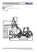
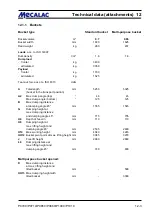
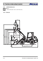
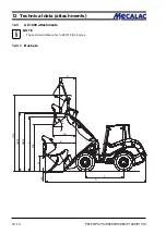
Страница 120: ...P0700 P0710 P0850 P0860 P1000 P1010 12 10 12 Technical data attachments L A H6 G H8 HH12 HH13 H10 B L6 A 2 D J 12 3 AX 1000 attachments NOTE The technical data refer to 365 70 R18 tyres 12 3 1 Buckets...

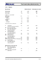
Страница 121: ...n A2 Max dump angle top 45 46 Max dump angle bottom 125 125 B Max dumping distance at dumping angle 45 mm 1545 1795 G Dumping height at max dumping distance and dumping angle 45 mm 710 475 H6 Depth of...

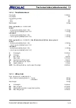
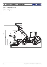
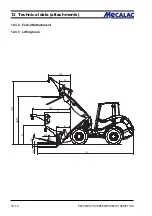
Страница 122: ...P0700 P0710 P0850 P0860 P1000 P1010 12 12 12 Technical data attachments A H6 500 A 5 G B C DD D EE HH15 HH N 12 3 2 Fork liftattachment 12 3 3 Lifting hook...

Страница 123: ...round stability factor 1 67 kg articulated level ground stability factor 1 25 2 700 kg uneven ground stability factor 1 67 kg A Total length 5 720 mm A5 Tilt angle 19 B Min reach 915 mm C Max reach 1...

Страница 124: ......

Страница 125: ...Additional options modifications Notes on inspection for loaders...

Страница 126: ...P070 P071 P085 P086 P100 P101 13 2 13 Additionaloptions modfications 13 Additional options modifica tions notes on inspection for loaders 13 1 Additionaloptions none 13 2 Modifications none...

Страница 127: ...P070 P071 P085 P086 P100 P101 13 3 Additionaloptions modfications 13...

Страница 128: ...P070 P071 P085 P086 P100 P101 13 4 13 Additionaloptions modfications...

Страница 129: ...P070 P071 P085 P086 P100 P101 13 5 Additionaloptions modfications 13...

Страница 130: ...P070 P071 P085 P086 P100 P101 13 6 13 Additionaloptions modfications...

Страница 131: ...P070 P071 P085 P086 P100 P101 13 7 Additionaloptions modfications 13...

Страница 132: ...P070 P071 P085 P086 P100 P101 13 8 13 Additionaloptions modfications...

Страница 133: ...P0700 P0710 P0850 P0860 P1000 P1010 Index i Index...

Страница 134: ...P0700 P0710 P0850 P0860 P1000 P1010 Index ii Index...

Страница 135: ...P0700 P0710 P0850 P0860 P1000 P1010 Index iii Index...

Страница 136: ...P0700 P0710 P0850 P0860 P1000 P1010 Index iv Index...

Страница 137: ...P0700 P0710 P0850 P0860 P1000 P1010 Index v Index...

Страница 138: ...P0700 P0710 P0850 P0860 P1000 P1010 Index vi Index...

Страница 139: ...P0700 P0710 P0850 P0860 P1000 P1010 Index vii Index...

Страница 140: ...P0700 P0710 P0850 P0860 P1000 P1010 Index viii Index...

Страница 141: ...P0700 P0710 P0850 P0860 P1000 P1010 Index ix Index...

Страница 142: ...P0700 P0710 P0850 P0860 P1000 P1010 Index x Index...

Страница 143: ...P0700 P0710 P0850 P0860 P1000 P1010 Index xi Index...

Страница 144: ...P0700 P0710 P0850 P0860 P1000 P1010 Index xii Index 23128003 Index 0...

Отзывы:

Похожие инструкции для AX 1000