User Manual
MEAS LT Level & Pressure Transducer User Manual
Measurement Specialties, Inc.
www.meas-spec.com
1-757-766-1500
1000 Lucas Way, Hampton, VA 23666 USA
20 of 31
1-800-745-8008
Appendix C: Transducer Field Checks
The following is a field check procedure for KPSI Level and Pressure Transducers. It is designed to
provide the information you need to isolate problems that may occur when deploying a transducer. These
checks will help eliminate the costly and time-consuming RMA process by determining in advance
whether the transducer is operating properly.
When a problem is encountered with a transducer, it is helpful to test the transducer independently from
the rest of the system, thereby establishing where to concentrate the troubleshooting effort. It is
important to determine if the fault lies in the transducer or the instrument reading the transducer signal,
i.e. digital panel meter, programmable logic controller, etc. If all of the following transducer tests deliver
normal results, the problem may be found elsewhere in your system.
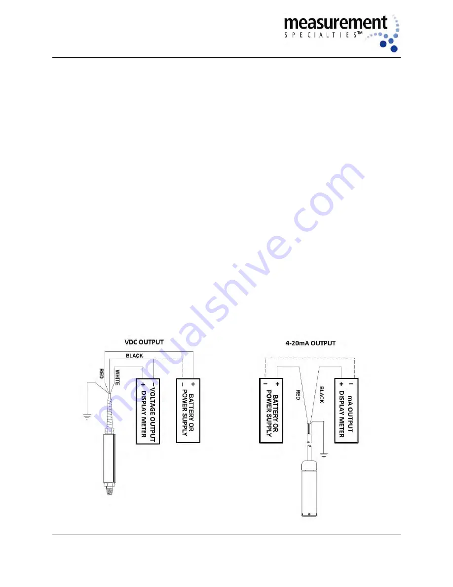
Below is a simple hookup diagram for the most common types of electrical output, a 0-5 VDC and a 4-20
mA transducers. The diagram above illustrates the attachment of the meter in series with the black
(negative signal) wire of the transducer using a 12-28 VDC power supply for transducer excitation. Some
suggested power supplies are:
(1) - 12 VDC automotive or lantern battery.
(2) - 6 VDC lantern batteries connected in series (for a total of 12 VDC).
(2) - 9 VDC transistor batteries connected in series (for a total of 18 VDC).
A laboratory-style linear power supply capable of 12VDC minimum

