background image

User Manual


MEAS LT Level & Pressure Transducer User Manual 


Measurement Specialties, Inc. 

www.meas-spec.com     

1-757-766-1500 

1000 Lucas Way, Hampton, VA 23666 USA  

24 of 31 

1-800-745-8008 

[email protected]


not  maintaining  the  desiccant  vent  filter  or  of  operating  the  transducer 

without  a  desiccant  filter  or  aneroid  bellows.  If  caught  early  enough,  the 

transducer can be saved by coiling the cable and transducer in a pan and 
baking it in an oven at 50

º

C (122

º

F) for a minimum of 2 hours. 

Be careful 

that  the  oven  temperature  does  not  exceed  50ºC  (122

º

F) 

or  both  the 

transducer  and the  cable  can  be  damaged. 

Alternatively

,  suspend  both 

the  cable  and  transducer  in  a  vertical  position  (with  vent  tube  down), 

overnight to allow water to drain from the transducer and vent tube. 


4. 

Symptom:


Transducer  suddenly  fails  during  or  just  after  a  nearby  lightning 

event. 


Procedure:

  This  failure  is  usually  caused  by  overvoltage  due  to  ground  transients 

resulting  from  a  direct  or  indirect  lightning  event.  These  transients  can 

travel distances of a mile or more.  The transducer may be returned to the 

factory for repair and optional retrofit of our 

lightning protection system. 

This system carries a lifetime warranty against transducer damage due to 

lightning. 


5. 

Symptom:


Transducer  response  to  pressure/level  input  changes 

becomes sluggish. 


Procedure:

  This is usually a sign that the sensing end of the transducer has become 

fouled with residue. The transducer must be removed from service and the 

sensing diaphragm cleaned as described in Item 2, (warm, soapy water). If 

fouling  persists,  the  transducer  may  be  replaced  with  a  Series  705  or 

Series  750  (non-  fouling)  transducer,  which  is  specifically  designed  for 

trouble-free operation in a high residue environment. 


6. 

Symptom:


Output reading is within limits but "freezes" at one point. 


Procedure:

  In  certain  environments  "crust"  may  form  over  the  sensing  diaphragm, 

preventing  the  sensor  from  identifying  change  in  level.  Removing  the 

transducer  from  service  and  cleaning  it  (as  described  in  Item  2)  will 

generally  solve  the  problem.  To  combat  marine  growth,  you  might  try 

wrapping  the  transducer  with  copper  wire  similar  to  that  found  in  wire 

scouring pads for cleaning dishes. 


Marine  growth  occurs  on  the  copper  and  eventually  erodes  the  copper 

and  drops  off  or  the  copper  is  manually  removed  during  routine 

maintenance.  Alternatively,  there  are  various  companies  that  will 

impregnate/coat  the  316  stainless  steel  with  anti-  fouling  chemicals  of 

coatings. Level  transducers temporarily removed from the  well  or  sump 

should not be stored dry, but should be stored in a bucket of fresh water 

Содержание MEAS LT

Страница 1: ...MEAS LT Level Pressure Transducers USER MANUAL 1st EDITION March 2013 ...

Страница 2: ...yurethane ETFE Jacketed Cable 5 Lightning Protection 6 Electrical Outputs 7 Cable Hanger 7 Submersible Cable Splicing Kit 7 3 0 INSTALLATION MAINTENANCE TIPS 8 General Installation Procedures 8 Transducer Anchors 8 Transducer Submersion 8 SuperDry Vent Filter Desiccant or Aneroid Bellow Installation 8 Cable Protection 9 Bending of Cable 9 Cable Compression 9 4 20 mA Wiring 9 VDC Wiring 10 Protecti...

Страница 3: ...ay Hampton VA 23666 USA 2 of 31 1 800 745 8008 WL sales meas spec com 4 0 WARRANTY PRODUCT RETURN PROCEDURE 13 Product Eligibility 13 Merchandise Return Procedures 13 APPENDIX A DRAWINGS DIAGRAMS 15 APPENDIX B FREQUENTLY ASKED QUESTIONS 17 APPENDIX C TRANSDUCER FIELD CHECKS TROUBLESHOOTING 20 APPENDIX D CALIBRATION CALCULATIONS 29 ...

Страница 4: ...g Our transducers are designed for rugged use However they need protection from over pressure and sharp impact Penetrate the surface slowly vertically and only to the depth necessary when lowering a transducer into a liquid Avoid dropping the unit from above the surface Clean all transducers by rinsing them in a mild detergent Direct probing of the diaphragm or attempts to remove protective screen...

Страница 5: ...bmersible level transducers and pressure transducers with molded cable attachment require an optional protective barrier that guards against moisture buildup in the cable vent tube The 810 SuperDry vent filter and the 815 Aneroid Bellows are guaranteed to operate maintenance free for one year The 815 Aneroid Bellows can be used on submersibles with accuracies of 0 25 FSO These barriers ensure reli...

Страница 6: ...4 mA at 14 70 psia The output of the transducer will need to be adjusted to compensate for the altitude difference with a separate barometric unit if necessary Polyurethane ETFE Jacketed Cable Most installations of our submersible level transducers connect our polyurethane or ETFE cable to a junction box From this junction box P N 840 users typically run their own cable to the required instrumenta...

Страница 7: ...ket The cable is fully shielded with the shield connected to the metal housing at the transducer end and terminated in a drain wire at the termination or user end The shield should always be terminated to a good earth ground unless the transducer is installed in an area where galvanic corrosion is known to be a serious problem Lightning Protection Lightning and surge protection for VDC and 4 20 mA...

Страница 8: ...secured to a hook on the well plate or an eye bolt may be attached to the side of the well casing The cable hanger loop is then secured to the eye bolt by using any number of types of fasteners A similar technique can be used when working in stilling wells for surface water level measurement In this case the loop end of the cable hanger can be attached directly to a screw or bolt bored into the st...

Страница 9: ... 06 00PC to clamp the transducer to a fixed object i e wall ladder step or require the unit to be suspended without any protective still well or attachment device In all installations care should be taken to ensure no damage occurs to the cable Transducer Submersion Damage to submersible cable is one of the most frequent causes of transducer failure Lower your transducer into the liquid slowly mak...

Страница 10: ...lation you do not crimp the vent tube inside the cable Consequently do not bend the cable more than a radius of 1 inch Cable Compression Many users require a compression fitting to secure our ETFE and polyurethane jacketed cable as it enters a junction box Care needs to be taken that you do not over tighten the fitting so as to damage the cable Compression fittings are not supplied by MEAS 4 20 mA...

Страница 11: ...f The protective cage diaphragm protector can easily be taken off by removing six 6 fasteners located on the bottom of the unit Position Sensitivity The transducer should be installed so that the diaphragm located behind the nose cap is oriented in a vertical position otherwise the unit could exhibit an offset General Maintenance Tips for Submersible Transducers Desiccant Maintenance WARNING POTEN...

Страница 12: ...g your pressure transducer ensure that all procedures have been followed in the proper cleaning of the cable and transducer to remove any hazardous materials The vent filter or bellows must be properly attached The cable should be coiled to ensure ease of handling and it must be protected against the possibility of accidental abrasion and or penetration of the cable jacket by sharp objects A lead ...

Страница 13: ...r diaphragm with your finger or any other object Also do not try to dry the inside portion of the transducer as you risk damaging the pressure sensor Step 3 Place the transducer in a vertical position with the sensing end facing downward in the bowl containing a mild cleaning solution for approximately 15 20 seconds Rinse in the bowl containing clean water and wipe dry the external casing only Pla...

Страница 14: ... Measurement Specialties Inc Hampton VA if your transducer is not operating properly Our staff is available for troubleshooting at 757 766 1500 or toll free at 1 800 745 8008 during normal working hours Eastern Time If your transducer or accessory needs to be returned to Measurement Specialties obtain a Returned Merchandise Authorization RMA from the Customer Service Department prior to shipment B...

Страница 15: ...e unsanitary or environmentally unsafe to handle If these guidelines are not met the package will be sent back unopened and at the customer s expense Please include the attached cable vent filter or aneroid bellow with each returned vented gage submersible transducer Measurement Specialties will return warranty items prepaid via UPS GROUND If the customer desires another method of return shipment ...

Страница 16: ...766 1500 1000 Lucas Way Hampton VA 23666 USA 15 of 31 1 800 745 8008 WL sales meas spec com Appendix A Drawings and Diagrams Wiring Diagrams for VDC and mA Outputs Notes These diagrams depict typical installations Refer to your power supply and instrumentation Manufacturer for the specifics of your application ...

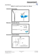
Страница 17: ...ucer User Manual Measurement Specialties Inc www meas spec com 1 757 766 1500 1000 Lucas Way Hampton VA 23666 USA 16 of 31 1 800 745 8008 WL sales meas spec com Cable Anchoring Schemes Reference Connection Schemes Submersible Cable Termination ...

Страница 18: ...re possible suspend the unit in a perforated 2 50 mm PVC pipe and thread the cable through protective conduit to the nearest junction box 3 Question I have an application where the transducer is frequently damaged by voltage spikes What can be done to prevent this Answer At a minimum make sure the cable shield is connected to an earth ground as near as possible to the transducer We can provide a s...

Страница 19: ...ts Unfortunately we not provide this service 8 Question Any ideas for preventing marine growth on your submersible transducers Answer You might want to try waterproof grease Remove the threaded nose cap to facilitate applying the grease Take care not to damage the diaphragm when applying the grease and not to trap air bubbles against the sensing diaphragm 9 Question How many measurements can you m...

Страница 20: ... You should mount it in a vertical position throughout the measurement cycle If you lay the transducer down the user must realize than an offset will occur 15 Question What happens when you freeze your transducer in a column of water Answer We have frozen our transducers in a container of water in a home freezer with no resulting damage However depending on the level range of the unit over pressur...

Страница 21: ...stablishing where to concentrate the troubleshooting effort It is important to determine if the fault lies in the transducer or the instrument reading the transducer signal i e digital panel meter programmable logic controller etc If all of the following transducer tests deliver normal results the problem may be found elsewhere in your system Below is a simple hookup diagram for the most common ty...

Страница 22: ...its note the results and continue to troubleshoot the transducer per the suggested measurements shown below Case check These checks diagrams on the next page are performed to detect internal shorts either in wiring that might have made contact with the structural components of the transducer or from water intrusion that has made its way to the internal circuit board In either case there should be ...

Страница 23: ...nd voltage requirements of any devices to be powered At 25ºC the 22 AWG conducting copper wire used in our polyurethane jacketed cable has a resistance of 16 45ohms per 1000 feet 304 m Using Ohms Law E IR where E voltage I current and R resistance one finds that a 20 mA signal requires 329 volts to drive it along 1000 feet 304 m of 22 AWG copper wire E 16 45 x 020 This drop is seen on both the sup...

Страница 24: ...into the transducer housing which can cause permanent damage If operational the cable can be repaired by using a splice kit P N 830 supplied by Measurement Specialties Inspect the transducer housing It should be intact and free of corrosion If the outer surface of the transducer is pitted this could be an indication of galvanic corrosion caused by stray ground currents If this is the case the tran...

Страница 25: ...gainst transducer damage due to lightning 5 Symptom Transducer response to pressure level input changes becomes sluggish Procedure This is usually a sign that the sensing end of the transducer has become fouled with residue The transducer must be removed from service and the sensing diaphragm cleaned as described in Item 2 warm soapy water If fouling persists the transducer may be replaced with a ...

Страница 26: ...le and into the transducer housing or lightning damage 9 Symptom Formation of marine growth on a submersible transducer Procedure Certain transducer construction materials for example 316 stainless steel attract marine life snails and algae Clean the transducer diaphragm by soaking it in a bucket of warm water with a non aggressive cleaning solution You can also coat the transducer with marine gre...

Страница 27: ...re Transducers User Manual I see the standard 4 20mA configuration Does the recording channel of my data logger become the mA meter Procedure Most data loggers cannot measure current mA directly When this is the case a load resistor must be used to convert the current mA output into an appropriate voltage If the User s Manual for your particular instrument does not illustrate a preferred method fo...

Страница 28: ...I have a MEAS LT 4 20mA transducer rated for 7 5 PSIG attached to a pressure source that is outputting 7 5 PSIG With 20VDC being supplied I am getting 19 94 mA I can t find the upper range allowance for the sensor but this seems low to me Does this mA reading fall into the acceptable range for the transducer with the settings I ve specified Procedure When evaluating a transducer it is sometimes co...

Страница 29: ...ue of milliamps 1 Divide the full scale range of the transducer in feet by 16 Record this value 2 Subtract 4 from the milliamp output of the transducer Record this value 3 Multiply the result of step 1 by the result of step 2 This is the approximate depth at which the transducer is sited If the resulting numbers are reasonably close to some verified value for current water depth then the unit is f...

Страница 30: ...e output by the transducer when it was being manufactured at several different pressures In addition two coefficients are provided that can be used to calculate the actual depth from any given mA output value These coefficients are derived from a Least Squares Best Fit Straight Line BFSL calibration using the data listed on the datasheet Our accuracy specification is referenced to the line describ...

Страница 31: ...User Manual MEAS LT Level Pressure Transducer User Manual Measurement Specialties Inc www meas spec com 1 757 766 1500 1000 Lucas Way Hampton VA 23666 USA 30 of 31 1 800 745 8008 WL sales meas spec com ...

Страница 32: ...case even though the offset or 0 PSIG output was 3 9565 mADC and the full scale point was 19 9310 mADC the unit actually performed better than its specified accuracy of 0 25 of full scale range as indicated in the Error FSO column and is called out as maximum static error 0 1764 FSO The calculation for pressure is illustrated below PSIG Span Output in mA Offset To convert to feet of water Feet H2O...

Страница 33: ...100 Lucas Way Hampton VA 23666 USA Office 757 766 1500 Toll Free 800 745 8008 Fax 757 766 4297 www meas spec com Email WL sales meas spec com Online orders www levelandpressure com ...

Отзывы: