Page 4 / IM 178
Unit Description
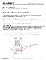
Typical Component Locations
Figure 1 shows a typical RDS unit with the location of the
major components and also lists some major dimensions.
Bottom Return Air
Opening
Bottom Discharge
Air Opening
Plan View
94.0
(2388)
Power & Control
Entrances
Outside & Return
Air Dampers
Exhaust
Hood
Main Control
Panel
Discharge Plenum
Cooling Coil
Outside Air
Louvers
Return
Air Fan
Supply Air Fan
Filter Section
Heat Section (Natural Gas,
Oil, Steam, Hot Water,
Electric)
Elevation
Figure 1. Typical component locations
These figures are for reference only. See the certified submit-
tals for actual specific dimensions.
Artisan Technology Group - Quality Instrumentation ... Guaranteed | (888) 88-SOURCE | www.artisantg.com