


IM 178 / Page 19
Charging the system
1. After all refrigerant piping is complete and the system has
been evacuated, it can be charged as described in the
paragraphs following. Connect the refrigerant drum to the
gauge port on the liquid shutoff valve, and purge the
charging line between the refrigerant cylinder and the valve.
Then open the valve to the midposition.
2. If the system is under a vacuum, stand the refrigerant
drum with the connection up, open the drum and break
the vacuum with refrigerant gas.
3. With a system gas pressure higher than the equivalent of
a freezing temperature, invert the charging cylinder and
elevate the drum above the condenser. With the drum in
this position and the valves open, liquid refrigerant will
flow into the condenser. Approximately 75% of the total
requirement estimated for the unit can be charged in this
manner.
4. After 75% of the required charge has entered the con-
denser, reconnect the refrigerant drum and charging line
to the suction side of the system. Again purge the con-
necting line, stand the drum with the connection side up,
and place the service valve in the open position.
Important: At this point, the charging procedure should be
interrupted and prestart checks made before attempting to
complete the refrigerant charge.
Note: It is recommended that the total operating charge per
circuit be stamped on the unit nameplate for future reference.
Refrigerant charge
Factory installed DX coils in RDS units are designed for use
with R-22. The total charge per circuit is the sum of three values:
1. Condensing unit charge — refer to manufacturer’s data.
2. Evaporator coil charge — refer to Table 6.
3. Charge for length of interconnecting piping, installed by
field — refer to Table 7.
Note: The systems consist of one refrigerant circuit on unit
size 800C and two refrigerant circuits containing identical
weights of refrigerant on unit size 802C. The values shown in
Tables 6 and 7 are for each circuit.
Note: The total operating charge per circuit should not
exceed the pumpdown capacity per circuit, specified by the
condensing unit manufacturer.
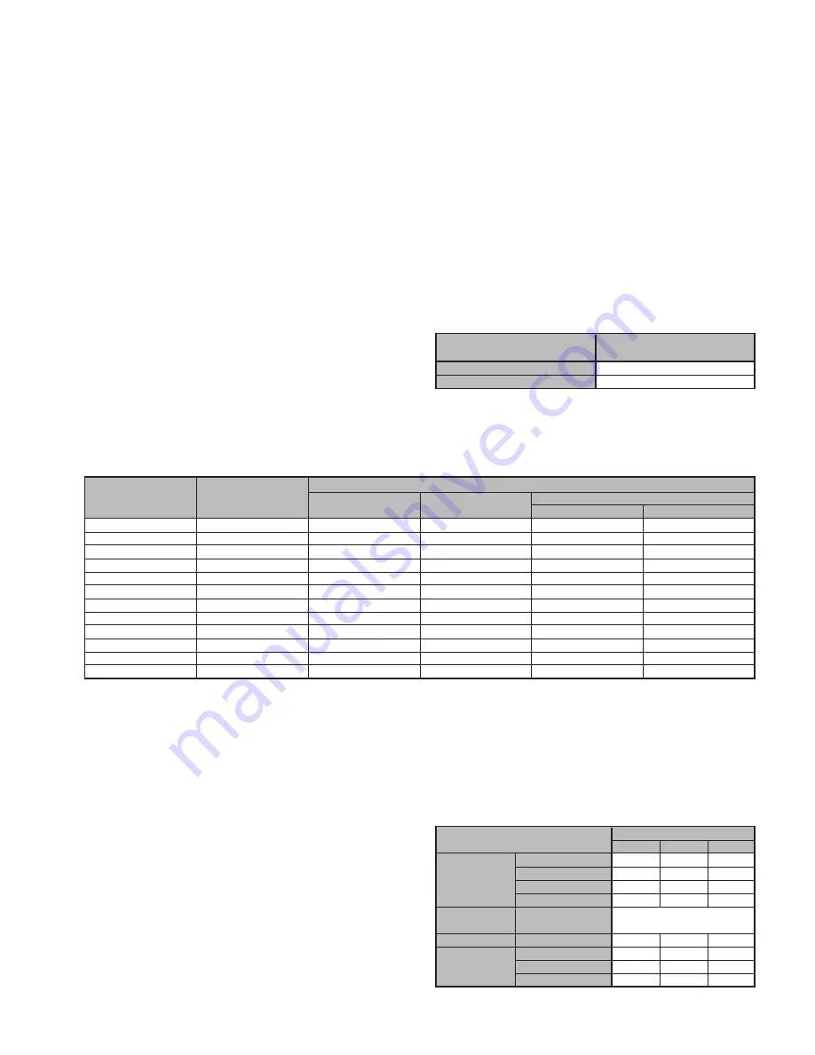
Table 6. Approximate refrigerant charge per circuit
EVAPORATOR COIL
UNIT SIZE
(LBS/CKT/COIL ROW)
800C
3.30
802C*
2.45
* The RDS 802C unit has two refrigerant circuits.
Table 7. Weight of refrigerant R-22 in copper lines (pounds per 100 feet of Type L tubing)
WEIGHT OF REFRIGERANT, LBS./100 FEET
O.D. LINE SIZE
VOL. PER 100 FT.
HOT GAS
SUCTION GAS (SUPERHEAT TO 85
°
F)
IN CUBIC FEET
LIQUID @ 100
°
F
@ 120
°
F COND.
20
°
F
40
°
F
3
⁄
8
"
0.054
3.84
0.202
0.052
0.077
1
⁄
2
"
0.100
7.12
0.374
0.098
0.143
5
⁄
8
"
0.162
7.12
0.605
0.158
0.232
7
⁄
8
"
0.336
24.00
1.260
0.323
0.480
1
1
⁄
8
"
0.573
40.80
2.140
0.550
0.820
1
3
⁄
8
"
0.872
62.10
3.260
0.839
1.250
1
5
⁄
8
"
1.237
88.00
4.620
1.190
1.770
2
1
⁄
8
"
2.147
153.00
8.040
2.060
3.060
2
5
⁄
8
"
3.312
236.00
12.400
3.180
4.720
3
1
⁄
8
"
4.728
336.00
17.700
4.550
6.750
3
5
⁄
8
"
6.398
456.00
24.000
6.150
9.140
4
1
⁄
8
"
8.313
592.00
31.100
8.000
11.190
Gas piping
See the “Installation” section of the gas-fired furnace instal-
lation manual, Bulletin No. IM 684 or 685.
Fuel oil piping
See the “Installation” section of the forced draft oil-fired
furnace installation manual, Bulletin No. IM 198.
Contractor coil piping
Contractor coils have fin height no greater than 36" (914 mm).
Coil connections are on the same side of the unit opposite
the drive. Refer to Table 8 for threaded connection sizes for
chilled water, hot water, and steam coils. Evaporator coil
connection sizes are based on the specific distributor and
Unit Piping
nozzle size selected for the given design conditions. See the
MS-85 Coil Selection Program output for sweat connection
information.
Table 8. Contractor coil connections based on fin height
CONTRACTOR COIL
CONNECTION SIZE
1.50 NPT 2.00 NPT 2.50 NPT
5WH, 5MH
12-36
—
—
CHILLED
5WL
12-18
21-30
33-36
WATER
5WS, 5MS
12-18
21-30
33-36
5WM, 5WD
—
—
12-36
EVAPORATOR
5E*
See MS-85
Coil Selection Output
HOT WATER
5W*, 1-Row
12-36
—
—
5GA, 5JA–1-Row
—
12-36
—
STEAM
5GA, 5JA–2-Row
—
—
12-36
8GA, 8JA
—
—
12-36
Artisan Technology Group - Quality Instrumentation ... Guaranteed | (888) 88-SOURCE | www.artisantg.com


