


Page 8 / IM 685
Gas Piping (Models 150 thru 200)
The gas piping cannot be routed up to the burner from within the curb on Models 150 through 200.
Gas piping must be routed across the roof to under the burner vestibule, or a pitch pocket can be
provided there. The installer must cut a hole in the bottom panel of the overhanging burner vestibule
through which to route the gas line up to the burner gas train. The bottom panel of the vestibule is at
approximately the same elevation as the top of the curb.
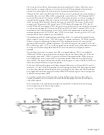
Gas Piping within the Vestibule
The gas piping layout within the vestibule will vary according to the complexity and size of the train
relative to the available room within the vestibule. As an example, a gas train with a high pressure
regulator and an extra safety shutoff valve (when required for IRI, etc.) will require careful use of the
available space. The examples shown in Figure 4 indicate typical piping layouts.
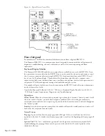
Field Gas Piping Required
The gas train components have all been factory installed and require only a connection to the supply gas
line. The manual shutoff valve is located within the burner vestibule. If local codes require a manual
shutoff valve that is accessible from outside the unit, that valve must be relocated or an additional valve
added. In locating such a valve, it is to be readily accessible and located such that no obstructions
interfere with operation of the handle. See Figure 16a, “Valve and Regulator Venting”, and “Normally
Open Vent Valves”.
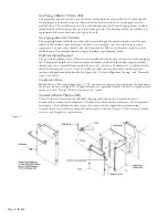
Condensate Drain
Models 020 and 025 are equipped with a
3
⁄
4
" I.P. condensate drain pipe projecting from the back side of
the furnace section (see Figure 14). If applicable codes or regulations require, this can be trapped and/or
routed to a drain. Also see "Furnace Condensation" section.
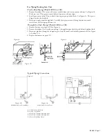
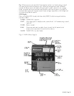
Vestibule (Models 150 thru 200)
These two furnace sizes exceed the allowable shipping width and for this reason the burner is
disconnected and removed for shipment. A sheetmetal vestibule weather enclosure is also disassembled
for shipment. At installation the burner must be re-mounted, the tagged electrical connections
re-attached, and the vestibule re-assembled and mounted as shown in Figure 5. These items are packed
in a crate and shipped as a separate item.
Figure 5.


