


Page 12 / IM 685
References
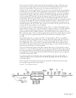
Figure 6a. Typical Electrical Schematic with RM7895A
Typical Sequence of Operation
When the rooftop unit is energized, 120 volt power is supplied through the system on-off switch (S1) to
burner on-off switch (S3) and to the (OBA3) contacts. Burner on-off switch (S3) will power the
modulating gas valve actuator (VM1) and terminal 5 (L1) on the flame safeguard (FSG). Upon a call for
heat, the control system will close (OBA3), thus energizing relay (R20). When 120 volt power is
furnished through the system on-off switch (S1), through the burner on-off switch (S3), through relay
(R20) contacts, through the high limit control (FLC) and through the optional automatic reset low gas
pressure switch (LP5) and the optional manual reset high gas pressure switch (HP5), terminal 6 on the
flame safeguard (FSG) is powered. The flame safeguard will go through a 10 second initiation period
before the prepurge period will begin.


