


IM 685 / Page 13
The air control valve will be at the minimum position during off cycles. Upon a call for heat or any
other time that a prepurge cycle occurs, the air control valve will be repositioned to the maximum
position for the prepurge and then returned to the minimum position for low fire start.
Through the N/C contacts for (R20) and (R23), the burner air and gas control valves are positioned to
minimum after a run cycle. When (R20) is energized for a new call for heat, (VM1) through the N/O
contacts of (R20) and the N/C contacts of (R21), will reposition the burner air valve to its maximum
open position for prepurge. When the air control valve reaches the full open position switch (LS2) is
'made', powering (FSG) terminal 7 through the burner air switch (AS). This initiates the 60 second
prepurge cycle. Concurrently, (LS2) powers timer (TD10) which will energize relay (R21) after 20
seconds. When (R21) is energized (VM1) will start the air control valve on its way toward the minimum
air valve position through the N/O contact of (R20) and (R21) and the N/C contact of (R23). At the
completion of the 60 second prepurge cycle the valve will be at the minimum open position and the
minimum position switch (LS1) will be "made". If (LS1) is not 'made', the start gas valves (GV1) will
not open and the burner will go out on safety lockout.
After completion of the 60 second prepurge period there will be a 10 second trial for ignition during
which terminal 8 (start gas valves - GV1) and terminal 10 (ignition transformer - IT) will be energized.
If flame is being detected through the flame rod (FD) at the completion of the 10 second trial for
ignition period, terminal 10 (ignition transformer - IT) will be de-energized and terminal 9 (relay coil -
R23 and main gas valves - GV4, etc.) will be energized and the control system will be allowed to control
the firing rate. The flame safeguard contains LEDs (lower left corner) that will glow to indicate
operation.
After the flame has lit and been proven, relay (R23) is energized allowing (VM1), as controlled by
(OBA4) and (OBA5), to position the burner air and gas valves for the required firing rate. When the
main control system closes (OBA5), the gas valve actuator will reposition toward a higher firing rate
until (OBA5) opens or the actuator reaches its maximum position. When the main control system
closes (OBA4), the actuator will reposition toward a lower firing rate. If neither (OBA4) or (OBA5) are
closed the actuator will remain at its present position.
In the event the flame fails to ignite or the flame safeguard fails to detect its flame within 10 seconds,
terminals 4, 8, 9 and 10 will be de-energized thus de-energizing the burner. The flame safeguard would
then be on safety lockout and would require manual resetting. The heat alarm relay (R24) would then
be energized and would then energize the remote HEAT FAIL indicator light and send a fail signal to
the MicroTech input board (ADI).
If an attempt is made to restart the burner by resetting the flame safeguard after a flame failure or
anytime an automatic restart is initiated, the earlier described prepurge cycle with the wide open air
valve will be repeated.
If the unit overheats, the combination fan–high limit control (FLC) will cycle the burner limiting
furnace temperature to the limit control set point.
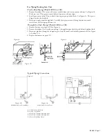
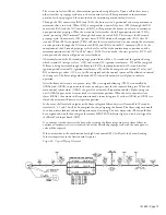
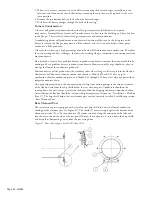
Figure 6b. Typical Piping Schematic


