


IM 685 / Page 27
BURNER OPERATES; HOWEVER . . .
4.1 Combution tests indicate
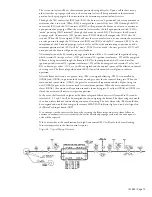
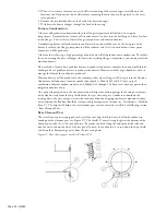
a. Measure gas manifold pressure at Port (1), Figure 16, both at the maximum and minimum firing rate and correct if
CO
2
and/or CO are not
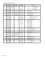
required. See Table 5, Column (9) and (10).
within the expected range.
b. Measure the burner air pressures at Port (4) and (5), Figure 16. If readings are significantly different, from Table 5,
Columns (6), (7), and (8) determine why. Possible reasons include a clogged blower wheel, air leaks, or loosened
components that could cause variations.
c. Combustion test should be performed when the furnace is at operating temperature (typically after 10 to 15 min.).
d. Models 040 and larger have multiple valves in parallel. Determine that they are all functioning. While operating at
maximum rate use the manual operator to momentarily close the valves one at a time while observing the manifold
pressure. If a reduction in manifold pressure does not occur the valve was not open before the test.
4.2 At maximum firing rate,
a. Gas manifold pressure is too high and furnace is being fired above its rated capacity. See "Verify Input Rate".
the burner runs rough.
Also check CO
2
and CO levels.
b. The heat exchanger needs cleaning. Increased pressure drop through heat exchanger reduces airflow and affects
combustion.
c. Inspect gun assembly and blast tube for warpage or deterioration.
4.3 Flame is not symmetrical
a. Too high airflow relative to gas flow. Check gas manifold pressure. Check CO
2
level.
as observed through rear
b. Gun disc is not perpendicular to the blast tube, or gun disc is warped or otherwise out of alignment.
inspection window.
4.4 Nuisance tripping of the
a. Check gas pressure situation. Marginal pressure during normal times can become low pressure during time of peak
flame safeguard.
demand and lead to trip-outs, etc. Pressures higher than that for which the gas train is designed can also cause
problems. Line pressure should not exceed 13.9" W.C. (
1
⁄
2
psi) into the combination gas controls. Pressures higher
than this require an additional stepdown regulator to maintain the pressure below 13.9" W.C. even at “no flow”
conditions. The prefered pressure to the combination gas controls is 7.0 in. W.C. A regulator that does not shut off
tight at “no flow” will allow a small amount of gas to leak past and eventually the high pressure will build up on the
downstream side, thus exceeding the rating of the gas train components.
b. Undersized piping can also cause problems by delivering reduced pressure during times of maximum demand.
c. Check the flame signal while modulating from minimum to maximum firing rate.
d. Check the ignition electrode gap and orientation. Check the porcelain for cracks or other defects.
e. Observe the flame signal DC volts when turning on the burner switch. Any indications before the ignition cycle could
indicate a short to ground. This could be an intermittent situation from moisture conditions. With line gas cock
closed any movement during the ignition attempt would indicate ignition interference.
f. Check supply voltage and if suspicion warrants arrange to have a recording voltmeter connected to the burner for a
period of time.
g. Marginal flame signal. Adjust flame rod position.
h. Check the ground path from FSG terminal G to the burner gun assembly. A wire runs from G to the ground screw on
the left side of the burner air box. The path continues through the variable orifice valve through the union to the
burner gun assembly.
4.5 Main flame comes
a. Check the burner fan air proving switch and tube. As the burner air control valve opens further to provide more air
on at low fire, but as
for an increased firing rate, the static pressure inside the air valve box is reduced. This is the pressure being sensed
actuator attempts to
by the air proving switch, and if it falls below its set point the burner will drop out. The adjustment screw is located
reposition for an increased
next to the wiring box cover. Turn screw CCW to reduce set point.
firing rate the flame goes
b. Use a manometer to determine if the gas pressure at the orifice is dropping prior to the flame going out. If gas
out. Then the sequence is
pressure is dropping, check for a plugged vent on a gas pressure regulator or something that restricts the gas flow
repeated.
in the line so only a low firing rate can occur. Also see 4.1d.
4.6 At the instant spark comes
a. Ignition interference. Flame rod or its wire is sensing voltage from ignition. Also verify that ignition electrode
on, the flame safeguard
spark gap is within specifications.
drops out and restarts the
pre-purge cycle.
4.7 When the flame safeguard
a. Purge card missing or bad, terminals are energized that should not be at that stage, or there is an internal system
is powered it locks out and
fault. Replace purge card or RM7895A as indicated.
the ALARM LED comes on.


