


IM 685 / Page 23
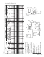
2.
Low CO
2
Readings –
Low CO
2
readings that cannot be corrected can be caused by air leaking into
the heat exchanger and diluting the flue gas. If this is suspected, take two consecutive CO
2
readings,
one with the supply fan running and one with the supply fan off. If the CO
2
increases with the
supply fan off, it could indicate leakage. Note that CO
2
samples must be taken from inside a tube,
not just from inside the flue box.
Checking for Leaks
1. Open up the rear casing panel while the unit is shut off and visually inspect the heat exchanger.
2. Visually inspect the heat exchanger while the burner is operating, looking for light coming through
holes. The burner should only be operated for a few minutes with the supply fan off, and take
necessary safety precautions around the hot heat exchanger.
3. Perform consecutive CO
2
tests with supply fan off and on. See Item 2 under “Leakage Symptoms.”
4.
Smoke Bomb Test –
Cover the flue box openings, open the rear casing panel so the heat exchanger
is accessible, toss a smoke bomb into the heat exchanger through the rear inspection port, replace the
port cover, and with a bright light look for smoke leaking through the heat exchanger. Remove the
remains of the smoke bomb and uncover the flue box openings before attempting to operate the
furnace.
Note:
In most cases small leaks in the heat exchanger are not a source of danger. Because the pressure
created by the supply fan is greater than that inside the heat exchanger, the leakage will be
into
the heat
exchanger, not
out of
the heat exchanger and into the airstream.
Causes of Failures
1.
Improper Application –
The furnace rating plate specifies a “Minimum Airflow CFM.” The furnace
must not be operated when airflow is below this minimum cfm. If the furnace is being used on a
variable air volume system, the control system must be such that the furnace will not operate when
the supply fan cfm has fallen below this minimum specified cfm. The furnace rating plate also
specifies a “Maximum MBH Input” which must not be exceeded. See “Verify Input Rate.”
2.
Control Failure –
The limit control does not function properly to shut off the burner when the heat
exchanger temperature becomes excessive. In most situations, a properly controlled unit will never
even require the limit control to shut off the unit. The limit control should be a backup control and
a problem attributed to a limit failure would generally indicate a control problem in addition to the
limit failure.
3.
Excessive Condensation –
Applications which will produce condensation require an all stainless steel
heat exchanger that is resistant to the effects of this condensation and that will give long heat
exchanger life. The likelihood of condensation increases with:
a. Colder supply air temperature across the secondary tubes, as on units taking in a lot of outdoor air
in colder weather.
b. Lower heat flow through the secondary tubes, as on modulating burners when operating at
reduced input.
c. High airflow across the secondary tubes such as any application with a low temperature rise
furnace.
4.
Chemical Deterioration –
Refrigerant leaks, some aerosol can propellants, fumes from dry cleaning
establishments, beauty shops, swimming pools, and others, often have detrimental effects on heat
exchangers when they get into the combustion air supply and thereby into the combustion. Even
fumes from nearby roof exhaust fans can cause problems.
5.
Inadequate or Distorted Airflow –
Internal baffles that have been repositioned or have loosened up
and moved can distort the airflow and cause failures. Construction rubbish, shipping cartons, and
insulation that has come loose will occasionally end up inside a unit and block airflow to part of the
furnace, resulting in a failure. These items can also alter the air or heat flow to the fan limit or some
other control and contribute to a failure.
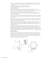
Replacing Heat Exchanger
1. Remove the complete flue box, the casing panel through which the flue tubes pass, and the rear
inspection cover. Open the hinged rear door.
2. The burner is mounted on and supported by the heat exchanger studs with four nuts. When
removing the heat exchanger, the burner must either be removed or blocked in place. Remove the
four burner mounting nuts and the two exchanger bolts located 2" above the upper burner mounting
nuts.


