McQuay IM 685 Скачать руководство пользователя страница 22

Page 22 / IM 685

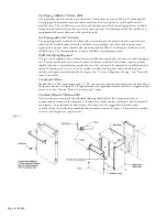
5. Reinstall the inspection door 

. Snug the screws but do not overtighten and crush the insulation.

6. Reinstall a turbulator in each tube approximately flush with the tube ends. The end of the

turbulators are formed such that the end will bind within the tube end and lock the turbulator in
place.

7. Reinstall flue box front wrap 

.

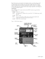
Figure 13. Models 032 thru 200 Heat Exchanger

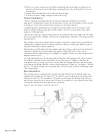
Models 020 thru 025 (see Figure 14)

1. To gain access to the inside of the combustion chamber, detach the burner from the furnace and set

it on the floor of the vestibule (see Figure 14, Item 

). The burner is attached to the furnace studs

with four nuts. Conduit lengths allows this movement of the burner without disconnecting wiring.
The union on the gas line must be opened.

2. Remove the flue box front wrap 

.

3. Remove and clean the turbulator 

 from each tube and clean the flue box.

4. Clean each tube with a 2

1

2

" round flue brush.

5. Remove the brushings and if required clean the combustion chamber and header through the burner

mounting tube.

6. Reinstall the burner.
7. Reinstall a turbulator in each tube approximately flush with the tube end, locking them in place with

the wedge clips on each turbulator.

8. Reinstall flue box front wrap 

.

Figure 14. Models 020 thru 025 Heat Exchanger

Leakage Symptoms

1.

Odor –

 Odors in the building are usually being brought in through the outdoor air intakes and do

not indicate leakage from the furnace. Check for down draft conditions and check the location of the
flue exhausts of other equipment that may be pulled into the outdoor air intake. A major and
obvious furnace rupture can be a source of odor. In general, small leaks in a furnace will not be a
source of odor or danger because the pressure created by the supply fan is greater than the pressure
inside the furnace. Therefore when the supply fan is operating, leakage will be 

into

 the furnace, not

out of

 the furnace and into the air stream. If the control system is such that the furnace comes on

and warms up the heat exchanger before the supply air fan comes on, and there is odor when the
supply fan first comes on, this could be caused by leakage. During the time the furnace is on and the
supply fan is off the leakage would be out off the furnace and then when the supply fan came on it
would blow those products of combustion into the supply duct.

Содержание IM 685

Страница 1: ...Gas Fired Furnace on McQuay Applied Rooftop Systems HT A with RM7895A Flame Safeguard Installation Maintenance Manual IM 685 Group Applied Systems Part Number 629948Y 00 Date March 1998 1998 McQuay I...

Страница 2: ...nty failure state the date of installation of the unit and the date of failure along with an explanation of the malfunctions and the description of the replacement parts required Parts are warranted f...

Страница 3: ...ssembly and requires no additional chimney flue pipe Breidert cap draft inducer etc Factory Mounting This burner and gas train has been installed and wired at the factory See Gas Piping Also note that...

Страница 4: ...the outside of the tube See Figure 1 Also apply a bead of high temperature silicone to seal both sides to the bottom of the flue box wrapper being careful not to obstruct the square drain holes in eac...

Страница 5: ...e burner is shown in Table 5 under Column 13 thru 15 Gas piping must be sized to provide the minimum required pressure at the burner when the burner is operating at maximum input Consult the appropria...

Страница 6: ...20 92 190 350 730 1100 2100 3300 5900 12000 30 73 152 285 590 890 1650 2700 4700 9700 40 63 130 245 500 760 1450 2300 4100 8300 50 56 115 215 440 670 1270 2000 3600 7400 60 50 105 195 400 610 1150 18...

Страница 7: ...s to avoid interference with swinging of doors etc Through the Curb Piping Models 020 thru 140 1 Remove bottom access panel See Figure 3c 2 Remove knockout and make an opening through bottom deck dire...

Страница 8: ...re only a connection to the supply gas line The manual shutoff valve is located within the burner vestibule If local codes require a manual shutoff valve that is accessible from outside the unit that...

Страница 9: ...tc 2 Review the equipment and service literature and become familiar with the location and purpose of the burner controls Determine where the gas and power can be turned off at the unit and upstream o...

Страница 10: ...electric gas valve in the line Open the gas line cocks upstream from there and bleed the gas line of all air Replace the 1 8 inch pipe plug 7 Leak check Using a rich soap water mixture and a brush ch...

Страница 11: ...until after a period of main flame operation has further purged the gas lines before trying to adjust out something that may actually be caused by air in the lines Modulate Firing Rates Set the tempe...

Страница 12: ...he flame safeguard FSG Upon a call for heat the control system will close OBA3 thus energizing relay R20 When 120 volt power is furnished through the system on off switch S1 through the burner on off...

Страница 13: ...flame rod FD at the completion of the 10 second trial for ignition period terminal 10 ignition transformer IT will be de energized and terminal 9 relay coil R23 and main gas valves GV4 etc will be ene...

Страница 14: ...history It can be mounted to the RM7895A and will retrieve information on the six most recent faults Consult the Honeywell bulletin 65 0090 1 7800 Series Keyboard Display Module and 65 0118 1 7800 Ser...

Страница 15: ...e RM7895A which are energized to indicate operation as follows POWER The RM7895A is powered PILOT The prepurge period is complete and the terminal for the start combination gas control is powered FLAM...

Страница 16: ...rly careful to correctly reinsert the air tube into the grommeted hole The tube should slip into the grommet so there is little leakage but it should not bear down on it or it can cause binding on the...

Страница 17: ...ure is not an option the following discussion on the High Pressure Regulator would still apply High Pressure Regulator If a high pressure regulator is included as part of the burner gas train or is in...

Страница 18: ...et that connects the air and gas valves must be correctly positioned on the control rod such that the bracket will be firmly held under tension against its stop when the actuator is in the minimum rat...

Страница 19: ...of 2000 feet and higher the gas burner must be derated 4 for every 1000 feet of altitude Example Model HT080 at an altitude of 3000 feet is derated 0 04 x 3 0 12 At 1000 mbh input 1000 x 0 12 120 mbh...

Страница 20: ...e adjusted to the flow rate used for this procedure is too high and must be reduced by repositioning the actuator to a lower firing rate or the gas supply line pressure is too low After adjusting valv...

Страница 21: ...will be diluted with outside air and lower readings will result If flue gas temperature is to be measured this must be done in the flue box not in the tube The temperature gradient within the tubes w...

Страница 22: ...bulator in each tube approximately flush with the tube end locking them in place with the wedge clips on each turbulator 8 Reinstall flue box front wrap Figure 14 Models 020 thru 025 Heat Exchanger Le...

Страница 23: ...Rate 2 Control Failure The limit control does not function properly to shut off the burner when the heat exchanger temperature becomes excessive In most situations a properly controlled unit will nev...

Страница 24: ...condensate However suitable steps should be taken to manage the flow of the condensate produced Most condensate will be produced in the secondary tubes where flue gas will sweep it into the flue box C...

Страница 25: ...eyboard display module or a DC voltmeter Twice Yearly 1 Burner Air Check burner fan wheel for dirt build up and lint Check combustion air intake louver and flue box for dirt buildup and accumulation o...

Страница 26: ...als 7 and L2 on the flame safeguard stays there the Keyboard when the burner fan is running Display Module indicates Purge Hold 2 2 Burner motor runs valve a Timer TD10 is not making after 20 seconds...

Страница 27: ...ressure will build up on the downstream side thus exceeding the rating of the gas train components b Undersized piping can also cause problems by delivering reduced pressure during times of maximum de...

Страница 28: ...64148A 04 040 Burner Gun Assembly 1 964148A 05 050 Burner Gun Assembly 1 964148A 06 064 065 Burner Gun Assembly 1 964148A 08 079 080 Burner Gun Assembly 1 964148A 10 100 Burner Gun Assembly 1 964148A...

Страница 29: ...N n i M M F C x a M R T F g e D g n i r u D e g r u p e r P e t a R x a M r e n r u B g n i t a r e p O e t a R x a M g n i r u D e g r u p e r P e t a R x a M x a M e t a R n i M e t a R 5 e t o N 5...

Страница 30: ...T t n e i b m A F g e D e r u t a r e p m e T s a G e u l F t n e c r e p 2 O C M P P O C C W n I x o B n i e r u s s e r P r i A Flue Gas Flue Gas s t n e m m o C y n a e z i r a m m u S k r o w e c...

Страница 31: ...IM 685 Page 31 Notes...

Страница 32: ...13600 Industrial Park Boulevard P O Box 1551 Minneapolis MN 55440 USA 612 553 5330...

Отзывы: