- 15 -
Mettre l'extrémité de l'arbre avec le trou vers le
côté avant droit de la machine côté reniflard
(#18).
11. Install
er le support d'arbre
(#7
)
côté poulie
,
et
(#18
)
côté hydraulique
.
Fixer chaque support avec
vis à tête hexagonale
(#23)
en utilisant
LOCTITE #243
sur le filetage et serrer avec un
couple de 17kN
Voir le shéma
#3
pour
l'application de
LOCTITE #515.
Laisser un jeu
de 0.5mm minimum pour l'arbre de renvoie une
fois que les vis sont installées et serrées au
couple
12.
Installer le raccord à 90°
(#2)
contenant la broche à
rouleau
(#20)
dans le support de l'arbre
(#18)
en
utilisant
LOCTITE
#565
sur les filetages
.
Assurez
vous que le support reniflard soit dirigé vers le
haut de la semelle
13.
Installer le reniflard
(#3)
sur le raccord 90°
(#2)
14. Install the exciter weights (#17) on the idler shaft (#8)
and secure with four socket head cap screws (#24)
using LOCTITE #243 thread locker sealant and
torque the cap screws to 32 ft.-lbs.
15. Press one bearing inner race onto one end of the
input shaft (#16).
Note: Make sure the bearings
and their inner races are kept as a matched set.
The flange on the inner race goes toward the
shoulder of the shaft.
16. Install the input gear (#10) onto the input shaft (#16)
and slide to the end with the bearing inner race.
17. Press the other bearing inner race onto the input
shaft (#16).
18. Install the input shaft subassembly into the baseplate
with the keyed end toward the left side (pulley side) of
the base plate.
19. Install the pulley side shaft cover (#9), containing the
shaft seal (#5) over the input shaft on the pulley side
of the baseplate.
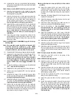
See the figure #3 for LOCTITE
#515 gasket maker application.
Lubricate the
input shaft seal and bearing with exciter oil
before inserting the input shaft through the oil
seal in the cover to prevent tearing the seal.
20. Secure the input shaft cover with the four flange head
crews (#23) using LOCTITE #243 thread locker
sealant on the bolt threads and torque the capscrews
to 13 ft.-lbs.
Refer to LOWER SHAFT ASSEMBLY, page 30.
21. Install the other input shaft cover (#12) and secure
with the four flange head screws (#22) using
LOCTITE #243 thread locker sealant and torque the
screws to 13 ft.-lbs.
See the figure #3 for LOCTITE
#515 gasket maker application. Check input shaft
for minimum of .020” end play after covers are
installed and the bolts are torqued.
22. Install one exciter weight (#17) to the input shaft on
the hydraulic housing side of the baseplate with two
socket head cap screws (#24) using LOCTITE #243
thread locker sealant and torque the cap screws to 30
ft.-lbs.
Be careful to use a small amount of thread
locker to avoid dripping it into the helix pin carrier
bearings at installation.
23. Slide the input gear (#10) toward the pulley side of
the input shaft (#16). The gears should not be
meshing at this time.
Refer to LOWER SHAFT ASSEMBLY, page 30.
24. Install the ball bearings (#3) and the spacer washer
(#7) onto the shift shaft (#10) and secure with the e-
clip (#5).
25. Press the shift shaft and ball bearing assembly into
the helix pin carrier (#9) and secure with the internal
retaining ring (#8).
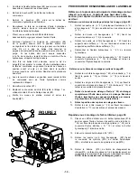
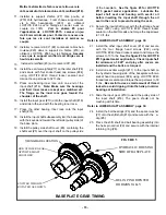
BASEPLATE GEAR TIMING
TIMING MARK LOCATION
HUB OF IDLER GEAR
OPPOSITE SHAFT
SHOULDER
EXCITER WEIGHTS
ROTATED AS SHOWN
HELIX PIN ORIENTED
HORIZONTALLY
HYDRAULIC HOUSING
SIDE OF BASEPLATE
FIGURE 5
Содержание 2900280
Страница 10: ...6...
Страница 31: ...4 15 10 3 5 9 8 7 11 19 18 14 6 2 0 21 22 13 16 17 1 22 2 12 Montage arbre inf rieur 26...
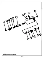
Страница 35: ...16 6 15 7 12 10 5 3 14 1 8 13 11 9 2 4 Boitier de commande 30...
Страница 42: ...NOTES 37...
Страница 43: ...NOTES 38...
Страница 52: ...6...
Страница 73: ...4 15 10 3 5 9 8 7 11 19 18 14 6 2 0 21 22 13 16 17 1 22 2 12 Montage arbre inf rieur 26...
Страница 77: ...16 6 15 7 12 10 5 3 14 1 8 13 11 9 2 4 Boitier de commande 30...
Страница 84: ...NOTES 37...
Страница 85: ...NOTES 38...
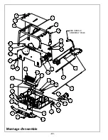
Страница 108: ...22 Montage d ensemble 6 1 66 0 3...
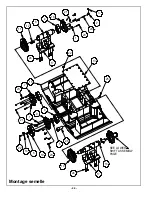
Страница 110: ...24 6 2 5 6 7 66 0 3 Montage semelle...
Страница 112: ...26 Montage arbre inf rieur...
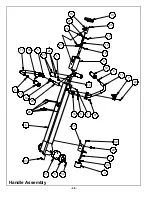
Страница 114: ...28 Handle Assembly...
Страница 116: ...30 Boitier de commande...
Страница 118: ...32 6 0 1 1 21 6 5 48 5 0 6 06 1 21 3 Gasoline Engine Assembly...
Страница 120: ...34 Diesel Engine Assembly...
Страница 123: ...37 NOTES...
Страница 124: ...38 NOTES...


