MBW 2900280 Скачать руководство пользователя страница 102

- 16 -

26. Lubricate the helix pin carrier/shift shaft assembly

with exciter oil and slide into the input shaft and install
the dowel pin (#11).

Note: Helix pin carrier MUST slide freely in input shaft.

27. Slide the helix pin/carrier to the middle of the helix

and orient the dowel pin parallel with the bottom of
the baseplate housing (#15).

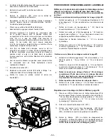
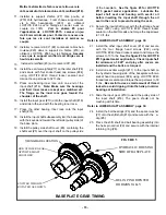
28. Align the timing marks on both gears and slide the

input gear over the helix pin/carrier and into mesh
with the gear on the idler shaft. Note position of
exciter weights (both weights in the down position)

See the figure #5 for setting the gear timing.

29. Install the other exciter weight (#17) to the input shaft

(#16) with two socket head cap screws (#24) using
LOCTITE #243 thread locker sealant on the threads
and torque the cap screws to 30 ft.-lbs.  

Be careful to

use a small amount of thread locker to avoid
dripping it into the helix pin carrier bearings at
installation.

30. Check the gear timing to assure free motion of the

shift shaft/helix pin carrier within the helix of the input
shaft for the full range of motion from one end of the
helix to the other.

Refer to LOWER SHAFT ASSEMBLY, page 30. for steps

#32 thru #42.

Note: The seals (#6), guide ring (#4), and gaskets (#17

and #18) should be replaced as a set.  MBW
recommends purchasing rebuild kit #17368 for ease
of repairs (Seals are pre-assembled to the spool).

31. If rebuild kit #17368 was purchased, skip to step #34.

32. Assemble the new seals (#6) to the shift spool (#15).

Note the orientation of the seal lips.  Hint:  use
hydraulic oil to lubricate the seal inner diameter
before pressing onto the spool.  Beware the slot
cut on the shift spool.  It may be sharp.  Press the
seal on “WITH” the slot and NOT “ACROSS” the
slot.

33. Thread the shift spool with seals onto the shift shaft

(#10).  

Note the left had thread.

34. Assemble the new guide ring (#4) to the shift spool.

35. Install a new mount gasket (#17) onto the hydraulic

housing (16).

36. Lubricate the inside of the hydraulic housing (#16)

and the seal lips with hydraulic oil.  

See Maintenance

section for hydraulic fluid type.

37. Install the hydraulic housing over the hydraulic seals

and guide ring.  

Be careful not to damage the guide

ring and hydraulic seals during installation.

38. Secure the mount plate (#20) over the hydraulic

housing (#16) to the input shaft cover (#12) with the
four flanged cap screws (#22) using LOCTITE #243
thread locker sealant on the threads and torque the
cap screws evenly in stages to 13 ft.-lbs.

  Make sure the bleeder screw port (#14) is in the vertical

position.

39. Install the gasket (#18) and cover (#19) to the

hydraulic housing (#16) with four hex head flange
screws (#21) using LOCTITE #243 thread locker
sealant on the threads and torque the cap screws to
76 in-lbs.

40. Install the 90 degree fitting (#13) into the port on the

hydraulic housing (#16).

41. Install the bleeder screw (#14) loosely into the port

fitting of the hydraulic housing.

42. Install the socket head pipe plug (#25) into the oil

drain port using LOCTITE #565 pipe sealant.

43. Pour in the exciter oil.  

Use only MBW Ground

Pounder Exciter Oil.  The amount of exciter oil
required is shown in the FLUID LEVELS section
of this manual.

44. Install the baseplate cover (#13) using LOCTITE

#515 gasket maker on the lip of the mounting surface
and secure with twenty hex head flange screws (#22)
using LOCTITE #243 on the threads.  

See the figure

#4 for LOCTITE #515 gasket maker application.

45. Install the key (#6) into the input shaft (#16).

46. Install the pulley (#19) with the longer hub shoulder

toward the baseplate housing.

47. Install the pulley mount washer (#14) and secure it to

the input shaft with the hex head flange screw (#22)
using LOCTITE #243 thread locker sealant on the
threads.

Refer to engine pages (Gasoline or Diesel)

48. Install the v-belt (#3 or #4) to the pulley of the

baseplate assembly.

Refer to Main Assembly, page 22.

49. Install the side cover (#12) on the pulley side of the

baseplate housing and secure with six hex head
flange screws (#22) using LOCTITE #243 thread
locker sealant.

50. Install the bellows (#3) into the bellows mount plate

(#14) and secure it to the baseplate with four hex
head flange screws (#23). Note spacer washers
(#28) between plates (#14).

51. Connect the hydraulic line (#21) to the 90 degree

fitting on the hydraulic housing.

52. Install the grommet (#2) into the hydraulic guard

(#13).

53. Guide the hydraulic line(#21) through the grommet

(#2) in the hydraulic guard (#13) and secure the
guard to the hydraulic side of the baseplate with the
four hex head flange screws (#22).  

Set the side

cover (#12) off to the side until bleeding and final
assembly is done.  The exciter is now ready for
final assembly.

Содержание 2900280

Страница 1: ...el listed GPR99 3090230 GPR135 2900280 REVERSIBLE MBW Inc 250 Hartford Rd PO Box 440 Slinger WI 53086 0440 Phone 262 644 5234 Fax 262 644 5169 Email mbw mbw com Website www mbw com MBW EUROPE Ltd Unit...

Страница 2: ...Assembly Procedure 14 Introduction 5 Control Head Assembly Procedure 17 Before Operation 5 Handle Assembly Procedure 17 Engine 5 Final Assembly 17 Starting Gasoline Engine 5 Diesel Engine Throttle Adj...

Страница 3: ...ORNIA PROPOSITION 65 WARNING Les gaz d chappement moteur et certains de ses constituants sont connus dans l tat de Californie pour causer le cancer des malformations cong nitales et d autres troubles...

Страница 4: ...D ALLUMAGE Les syst mes d allumage sans rupteur avec magn to et batterie peuvent provoquer de s rieuses lectrocutions viter tout contact avec ces l ments ou leurs c bles V TEMENTS Ne pas porter de v t...

Страница 5: ...devices are in place Wear approved hearing protection foot protection eyeprotection and head protection U S PATENT 7 165 469 STOP 19326HYDRAULICPLATE SHUT OFF themotor before servic ing or cleaning DO...

Страница 6: ...use engine stop switch close fuel valve RE VE RS E CAUTION 14 665 SHUT OFFthe motor before servic ing or cleaning DO NOT RUN in an enclosed area The engine produces carbon monoxide a POISONOUS GAS 15...

Страница 7: ...358 kg 400 kg MOTEUR Honda GX390 388 cm 3 Honda GX390 388 cm 3 Hatz 1B40 462 cm 3 FUEL Gas Gas Diesel R gime MOTEUR 3600 t min 3600 t min 3600 t min D marreur Lanceur Lanceur Electrique et Lanceur EX...

Страница 8: ...ge NIVEAU D HUILE Contr ler le niveau d huile du moteur Pour plus d informations voir le paragraphe Lubrification dans le manuel du moteur ou le paragraphe MAINTENANCE PERIODIQUE dans ce manuel FILTRE...

Страница 9: ...r DIESEL Ramenez l acc l rateur en position STOP 4 Fermer l arriv e carburant lorsque cela est applicable LEVAGE ET TRANSPORT 1 Soulevez l unit par anneau de levage central sur arceau 2 La machine doi...

Страница 10: ...6...

Страница 11: ...hanger l huile X X Resserrer les boulons1 X X Hydraulique Contr le niveau et correction X Quincaillerie Contr le et resserage si besoin1 X X Sillent Block Contr le craquelure X X 1 V rifier toute la v...

Страница 12: ...limination inad quate des batteries peut entra ner la contamination des sols et des eaux souterraines Charge Batterie 1 Si l appareil n est pas utilis r guli rement charger votre batterie peut tre n...

Страница 13: ...cription 16129 Tapis de test en caoutchouc 16031 Jeu d autocollants 17368 Kit reconstrution hydraulique Base 19606 Kit reconstrution hydraulique Haut Proc dure de d montage MOTEUR DIESEL Se r f rer au...

Страница 14: ...et le raccord sur la t te de commande exempts de salet et de d bris l aide de ruban adh sif Veillez utiliser un bac pour recuperer l huile hydraulique 8 Utiliser le crochet de levage sur l arceau de s...

Страница 15: ...mplacer si n cessaire 13 Nettoyer et inspecter la bobine 15 et le bo tier hydraulique 16 14 R installer la vis de purge 14 sur le bo tier hydraulique 16 15 Installez le nouveau joint du cylindre 18 le...

Страница 16: ...vis n 37 les plaques d extension n 9 et les bagues n 10 le cas echeant sur les c tes du socle n 5 2 Retirer les douze vis hexagonales n 22 fixant les couvercles lateraux n 12 la semelle 3 Retirez les...

Страница 17: ...montage complet ou reconstruction 29 Retirer la bague de retenue interne 8 partir du support d axe h lico dale 9 et enlever l arbre d inversion 10 et les roulements 3 comme un sous ensemble 30 Enleve...

Страница 18: ...le assorti 2 Inspectez tous les paliers les arbres porte broche helico dale et engrenages pour contr le de l usure les debris et la decoloration de la chaleur Remplacez au besoin Remplacer les rouleme...

Страница 19: ...assembly into the baseplate with the keyed end toward the left side pulley side of the base plate 19 Install the pulley side shaft cover 9 containing the shaft seal 5 over the input shaft on the pulle...

Страница 20: ...tion 38 Secure the mount plate 20 over the hydraulic housing 16 to the input shaft cover 12 with the four flanged cap screws 22 using LOCTITE 243 thread locker sealant on the threads and torque the ca...

Страница 21: ...ock nut 26 2 Assemble shift bracket 10 to shift linkage 16 with shoulder bolt 18 washer 27 and lock nut 26 3 Install the control head assembly 9 into the handle tube 8 with four flange lock screws 28...

Страница 22: ...e Belt Adjustment section of this manual to complete assembly 13 Secure hydraulic line 21 to control head fitting 14 Bleed the hydraulics according to the Bleeding and Adjustment of Hydraulic Controls...

Страница 23: ...Worn belt replace belt 3 Clutch malfunction replace clutch 1 Too much hydraulic fluid in control head set fluid level per Bleeding and Adjustment of Hydraulic Controls section of this manual 2 Belt i...

Страница 24: ...rer s Owner s Manual Hardware Replace any worn or damaged hardware as needed Replacement hardware should be grade 5 and zinc plated unless otherwise specified Safety Decals Replace if they become dama...

Страница 25: ...and to carry an adequate parts stock in all areas of the country Their sales engineers are available for professional consultation If you cannot locate an MBW distributor in your area contact MBW or o...

Страница 26: ...as shown above Write Model Number here Write Serial Number here Contact Information MBW Inc 250 Hartford Rd PO Box 440 Slinger WI 53086 0440 Phone 262 644 5234 Fax 262 644 5169 Email mbw mbw com Webs...

Страница 27: ...25 6 7 26 11 1 9 SEE HANDLE ASSEMBLY PAGE 29 23 31 15 30 20 3 2 3 4 17 35 3 4 23 27 14 28 21 13 2 24 22 18 5 1 12 22 8 35 34 16 33 9 37 3 6 1 0 Montage d ensemble 22...

Страница 28: ...LETE 1 1 1 1 18 19479 THROTTLE CABLE 1 1 1 1 19 19535 ROLLCAGE 1 1 1 1 20 19537 ENGINE DECK 1 19538 ENGINE DECK 1 1 20317 ENGINE DECK 1 21 19790 HOSE HYDRAULIC 1 1 1 1 22 F042004FWS FWS 1 4 20 x 1 2 Z...

Страница 29: ...21 3 18 4 8 12 11 2 2 0 23 1 22 24 17 13 25 15 7 23 4 9 1 21 26 5 22 14 6 19 23 SEE LOWER SHIFT ASSEMBLY PAGE 16 10 24 17 Montage semelle 24...

Страница 30: ...1 1 15 16 16331 16599 BASEPLATE MACHINED INPUT SHAFT 1 1 1 1 1 1 17 16608 16260 EXCITER WEIGHT GPR99 EXCITER WEIGHT GPR135 4 4 18 20312 17104 EXCITER WEIGHT GPR160 BEARING COVER EXCITER BREATHER 1 1 4...

Страница 31: ...4 15 10 3 5 9 8 7 11 19 18 14 6 2 0 21 22 13 16 17 1 22 2 12 Montage arbre inf rieur 26...

Страница 32: ...2 HELIX PIN CARRIER SHIFT SHAFT 1 1 11 12 16254 16264 DOWEL PIN M10 x 70 BEARING COVER EXCITER 1 1 13 14 16446 17023 FITTING 90DEGREE PARKER KIT BLEEDER SCREW 1 1 15 16 17275 17276 SHIFT SPOOL HOUSING...

Страница 33: ...10 13 27 25 26 27 1 7 3 0 5 24 23 18 16 18 1 9 19 4 11 7 22 12 4 19 14 20 28 14 5 1 31 8 15 32 29 2 33 32 2 1 6 3 4 3 Handle Assembly 28...

Страница 34: ...19422 CONTROL HANDLE 1 18 19442 SHOULDER BOLT 5 16 x 3 4 1 4 20 2 19 19519 HANDLE GRIP 1 00 I D x 4 1 2 FOAM 3 20 19526 SHAFT CONTROL 1 21 19533 SHOCK MOUNT HANDLE 2 22 F023204FSS FLAT SOCKET HEAD SR...

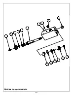
Страница 35: ...16 6 15 7 12 10 5 3 14 1 8 13 11 9 2 4 Boitier de commande 30...

Страница 36: ...ITTING SOCKET HEAD PLUG 1 1 7 8 19427 19430 HOUSING CONTROL HEAD SHAFT WIPER SEAL 1 1 9 10 19431 19433 HYDRAULIC SHAFT SEAL BEARING GUIDE RING 1 1 11 12 19434 19527 BEARING GUIDE RING PISTON SHAFT 1 1...

Страница 37: ...3 9 11 6 5 12 2 7 15 14 8 13 16 1 10 4 SHIM ENGINE ONLY AS REQUIRED 015 MAX SHIMS ANY ONE PLACE Gasoline Engine Assembly 32...

Страница 38: ...CER CLUTCH 1 1 1 1 7 8 16665 16676 WASHER MOUNT BELT GUARD 1 1 1 1 9 10 16974 17467 HOSE OIL DRAIN BELT GUARD MOUNT 1 1 1 1 11 12 F052408FSS F061618HCS FSS 5 16 24 x 1 ZP HCS 3 8 16 x 2 1 4 GR 5 ZP 4...

Страница 39: ...14 6 16 36 1 8 33 12 11 29 30 17 31 2 23 4 7 24 35 13 32 3 1 0 27 25 25 19 26 5 21 25 24 26 9 22 18 15 34 37 37 34 28 20 Diesel Engine Assembly 34...

Страница 40: ...ATTERY BOX 1 21 19547 MOUNT BATTERY BOX 2 22 19549 BRACKET BATTERY HOLD DOWN 1 23 19551 BATTERY 12 VOLT SIZE U1 300CCA BUY LOCALLY HAZARDOUS TO SHIP 1 24 F042006FWS FWS 1 4 20 x 1 ZP 6 25 F0420ELN LOC...

Страница 41: ...5 This warranty does not cover the cost of transportation and other expenses which may be connected with warranty service but not specifically mentioned herein 6 This warranty does not cover any upda...

Страница 42: ...NOTES 37...

Страница 43: ...NOTES 38...

Страница 44: ...uid 8 Service 9 Torque Chart 9 Service Tools 9 Main Disassembly Procedure Diesel Engine 9 Main Disassembly Procedure Gasoline Engine 10 Exciter Oil Change Procedure 10 Lower Hydraulic Seal Replacement...

Страница 45: ...ORNIA PROPOSITION 65 WARNING Les gaz d chappement moteur et certains de ses constituants sont connus dans l tat de Californie pour causer le cancer des malformations cong nitales et d autres troubles...

Страница 46: ...D ALLUMAGE Les syst mes d allumage sans rupteur avec magn to et batterie peuvent provoquer de s rieuses lectrocutions viter tout contact avec ces l ments ou leurs c bles V TEMENTS Ne pas porter de v t...

Страница 47: ...devices are in place Wear approved hearing protection foot protection eyeprotection and head protection U S PATENT 7 165 469 STOP 19326HYDRAULICPLATE SHUT OFF themotor before servic ing or cleaning DO...

Страница 48: ...use engine stop switch close fuel valve RE VE RS E CAUTION 14 665 SHUT OFFthe motor before servic ing or cleaning DO NOT RUN in an enclosed area The engine produces carbon monoxide a POISONOUS GAS 15...

Страница 49: ...358 kg 400 kg MOTEUR Honda GX390 388 cm 3 Honda GX390 388 cm 3 Hatz 1B40 462 cm 3 FUEL Gas Gas Diesel R gime MOTEUR 3600 t min 3600 t min 3600 t min D marreur Lanceur Lanceur Electrique et Lanceur EX...

Страница 50: ...ge NIVEAU D HUILE Contr ler le niveau d huile du moteur Pour plus d informations voir le paragraphe Lubrification dans le manuel du moteur ou le paragraphe MAINTENANCE PERIODIQUE dans ce manuel FILTRE...

Страница 51: ...r DIESEL Ramenez l acc l rateur en position STOP 4 Fermer l arriv e carburant lorsque cela est applicable LEVAGE ET TRANSPORT 1 Soulevez l unit par anneau de levage central sur arceau 2 La machine doi...

Страница 52: ...6...

Страница 53: ...hanger l huile X X Resserrer les boulons1 X X Hydraulique Contr le niveau et correction X Quincaillerie Contr le et resserage si besoin1 X X Sillent Block Contr le craquelure X X 1 V rifier toute la v...

Страница 54: ...limination inad quate des batteries peut entra ner la contamination des sols et des eaux souterraines Charge Batterie 1 Si l appareil n est pas utilis r guli rement charger votre batterie peut tre n...

Страница 55: ...cription 16129 Tapis de test en caoutchouc 16031 Jeu d autocollants 17368 Kit reconstrution hydraulique Base 19606 Kit reconstrution hydraulique Haut Proc dure de d montage MOTEUR DIESEL Se r f rer au...

Страница 56: ...et le raccord sur la t te de commande exempts de salet et de d bris l aide de ruban adh sif Veillez utiliser un bac pour recuperer l huile hydraulique 8 Utiliser le crochet de levage sur l arceau de s...

Страница 57: ...mplacer si n cessaire 13 Nettoyer et inspecter la bobine 15 et le bo tier hydraulique 16 14 R installer la vis de purge 14 sur le bo tier hydraulique 16 15 Installez le nouveau joint du cylindre 18 le...

Страница 58: ...vis n 37 les plaques d extension n 9 et les bagues n 10 le cas echeant sur les c tes du socle n 5 2 Retirer les douze vis hexagonales n 22 fixant les couvercles lateraux n 12 la semelle 3 Retirez les...

Страница 59: ...montage complet ou reconstruction 29 Retirer la bague de retenue interne 8 partir du support d axe h lico dale 9 et enlever l arbre d inversion 10 et les roulements 3 comme un sous ensemble 30 Enleve...

Страница 60: ...le assorti 2 Inspectez tous les paliers les arbres porte broche helico dale et engrenages pour contr le de l usure les debris et la decoloration de la chaleur Remplacez au besoin Remplacer les rouleme...

Страница 61: ...assembly into the baseplate with the keyed end toward the left side pulley side of the base plate 19 Install the pulley side shaft cover 9 containing the shaft seal 5 over the input shaft on the pulle...

Страница 62: ...tion 38 Secure the mount plate 20 over the hydraulic housing 16 to the input shaft cover 12 with the four flanged cap screws 22 using LOCTITE 243 thread locker sealant on the threads and torque the ca...

Страница 63: ...ock nut 26 2 Assemble shift bracket 10 to shift linkage 16 with shoulder bolt 18 washer 27 and lock nut 26 3 Install the control head assembly 9 into the handle tube 8 with four flange lock screws 28...

Страница 64: ...e Belt Adjustment section of this manual to complete assembly 13 Secure hydraulic line 21 to control head fitting 14 Bleed the hydraulics according to the Bleeding and Adjustment of Hydraulic Controls...

Страница 65: ...Worn belt replace belt 3 Clutch malfunction replace clutch 1 Too much hydraulic fluid in control head set fluid level per Bleeding and Adjustment of Hydraulic Controls section of this manual 2 Belt i...

Страница 66: ...rer s Owner s Manual Hardware Replace any worn or damaged hardware as needed Replacement hardware should be grade 5 and zinc plated unless otherwise specified Safety Decals Replace if they become dama...

Страница 67: ...and to carry an adequate parts stock in all areas of the country Their sales engineers are available for professional consultation If you cannot locate an MBW distributor in your area contact MBW or o...

Страница 68: ...as shown above Write Model Number here Write Serial Number here Contact Information MBW Inc 250 Hartford Rd PO Box 440 Slinger WI 53086 0440 Phone 262 644 5234 Fax 262 644 5169 Email mbw mbw com Webs...

Страница 69: ...25 6 7 26 11 1 9 SEE HANDLE ASSEMBLY PAGE 29 23 31 15 30 20 3 2 3 4 17 35 3 4 23 27 14 28 21 13 2 24 22 18 5 1 12 22 8 35 34 16 33 9 37 3 6 1 0 Montage d ensemble 22...

Страница 70: ...LETE 1 1 1 1 18 19479 THROTTLE CABLE 1 1 1 1 19 19535 ROLLCAGE 1 1 1 1 20 19537 ENGINE DECK 1 19538 ENGINE DECK 1 1 20317 ENGINE DECK 1 21 19790 HOSE HYDRAULIC 1 1 1 1 22 F042004FWS FWS 1 4 20 x 1 2 Z...

Страница 71: ...21 3 18 4 8 12 11 2 2 0 23 1 22 24 17 13 25 15 7 23 4 9 1 21 26 5 22 14 6 19 23 SEE LOWER SHIFT ASSEMBLY PAGE 16 10 24 17 Montage semelle 24...

Страница 72: ...1 1 15 16 16331 16599 BASEPLATE MACHINED INPUT SHAFT 1 1 1 1 1 1 17 16608 16260 EXCITER WEIGHT GPR99 EXCITER WEIGHT GPR135 4 4 18 20312 17104 EXCITER WEIGHT GPR160 BEARING COVER EXCITER BREATHER 1 1 4...

Страница 73: ...4 15 10 3 5 9 8 7 11 19 18 14 6 2 0 21 22 13 16 17 1 22 2 12 Montage arbre inf rieur 26...

Страница 74: ...2 HELIX PIN CARRIER SHIFT SHAFT 1 1 11 12 16254 16264 DOWEL PIN M10 x 70 BEARING COVER EXCITER 1 1 13 14 16446 17023 FITTING 90DEGREE PARKER KIT BLEEDER SCREW 1 1 15 16 17275 17276 SHIFT SPOOL HOUSING...

Страница 75: ...10 13 27 25 26 27 1 7 3 0 5 24 23 18 16 18 1 9 19 4 11 7 22 12 4 19 14 20 28 14 5 1 31 8 15 32 29 2 33 32 2 1 6 3 4 3 Handle Assembly 28...

Страница 76: ...19422 CONTROL HANDLE 1 18 19442 SHOULDER BOLT 5 16 x 3 4 1 4 20 2 19 19519 HANDLE GRIP 1 00 I D x 4 1 2 FOAM 3 20 19526 SHAFT CONTROL 1 21 19533 SHOCK MOUNT HANDLE 2 22 F023204FSS FLAT SOCKET HEAD SR...

Страница 77: ...16 6 15 7 12 10 5 3 14 1 8 13 11 9 2 4 Boitier de commande 30...

Страница 78: ...ITTING SOCKET HEAD PLUG 1 1 7 8 19427 19430 HOUSING CONTROL HEAD SHAFT WIPER SEAL 1 1 9 10 19431 19433 HYDRAULIC SHAFT SEAL BEARING GUIDE RING 1 1 11 12 19434 19527 BEARING GUIDE RING PISTON SHAFT 1 1...

Страница 79: ...3 9 11 6 5 12 2 7 15 14 8 13 16 1 10 4 SHIM ENGINE ONLY AS REQUIRED 015 MAX SHIMS ANY ONE PLACE Gasoline Engine Assembly 32...

Страница 80: ...CER CLUTCH 1 1 1 1 7 8 16665 16676 WASHER MOUNT BELT GUARD 1 1 1 1 9 10 16974 17467 HOSE OIL DRAIN BELT GUARD MOUNT 1 1 1 1 11 12 F052408FSS F061618HCS FSS 5 16 24 x 1 ZP HCS 3 8 16 x 2 1 4 GR 5 ZP 4...

Страница 81: ...14 6 16 36 1 8 33 12 11 29 30 17 31 2 23 4 7 24 35 13 32 3 1 0 27 25 25 19 26 5 21 25 24 26 9 22 18 15 34 37 37 34 28 20 Diesel Engine Assembly 34...

Страница 82: ...ATTERY BOX 1 21 19547 MOUNT BATTERY BOX 2 22 19549 BRACKET BATTERY HOLD DOWN 1 23 19551 BATTERY 12 VOLT SIZE U1 300CCA BUY LOCALLY HAZARDOUS TO SHIP 1 24 F042006FWS FWS 1 4 20 x 1 ZP 6 25 F0420ELN LOC...

Страница 83: ...5 This warranty does not cover the cost of transportation and other expenses which may be connected with warranty service but not specifically mentioned herein 6 This warranty does not cover any upda...

Страница 84: ...NOTES 37...

Страница 85: ...NOTES 38...

Страница 86: ...ION 65 WARNING Les gaz d chappement moteur et certains de ses constituants sont connus dans l tat de Californie pour causer le cancer des malformations cong nitales et d autres troubles de la reproduc...

Страница 87: ...E Les syst mes d allumage sans rupteur avec magn to et batterie peuvent provoquer de s rieuses lectrocutions viter tout contact avec ces l ments ou leurs c bles V TEMENTS Ne pas porter de v tements l...

Страница 88: ...During operation run engine at full throttle when excessive kickback is noticed maximum compaction has been reached 8 To stop return throttle to the idle position and allow engine to idle for one min...

Страница 89: ...ARD REVERSE 14665 HYDRAULIC OIL 15844 13483 CAUTION Wear approved hearing protection foot protection eye protection and head protection STOP Read the Operating Instructions before operating this piece...

Страница 90: ...IFUGE 44 kN 60kN 60kN EXCITEUR VPM 3840 vpm 3840 vpm 3840 vpm TRAVEL SPEED 24 m min 24 m min 23 m min PROFONDEUR 71 cm 71 cm 71 cm Longueur x largeur 50 x 95 cm 50 x 95 cm 50 x 95 cm POIDS 352 kg 358...

Страница 91: ...rrage NIVEAU D HUILE Contr ler le niveau d huile du moteur Pour plus d informations voir le paragraphe Lubrification dans le manuel du moteur ou le paragraphe MAINTENANCE PERIODIQUE dans ce manuel FIL...

Страница 92: ...acc l rateur en position STOP 4 Fermer l arriv e carburant lorsque cela est applicable LEVAGE ET TRANSPORT 1 Soulevez l unit par anneau de levage central sur arceau 2 La machine doit tre transport e...

Страница 93: ...f rer au manuel d entretien du fabricant moteur pour les intervalles de maintenance et proc dures Nettoyage de la plaque Retirez tout exc s de d bris pouvant entrer dans le carter de l appareil SYSTE...

Страница 94: ...s et des eaux souterraines Charge Batterie 1 Si l appareil n est pas utilis r guli rement charger votre batterie peut tre n cessaire Une batterie inutilis e se d chargent au fil du temps Les batteries...

Страница 95: ...extr mit du flexible et t te de raccord du boitier de commande exempts de salet et des d bris l aide de ruban adh sif Attention utiliser un bac pour r cup rer l huile hydraulique 8 Utilisez le crochet...

Страница 96: ...f Veillez utiliser un bac pour r cup rer l huile hydraulique 8 Utiliser le crochet de levage sur l arceau de s curit 19 pour s parer la platine moteur de la base de la plaque Soyez prudent pour guider...

Страница 97: ...Remplacer si n cessaire 13 Nettoyer et inspecter la bobine 15 et le bo tier hydraulique 16 14 R installer la vis de purge 14 sur le bo tier hydraulique 16 15 Installez le nouveau joint du cylindre 18...

Страница 98: ...es plaques d extension n 9 et les bagues n 10 le cas ch ant sur les c t s du socle n 5 2 Retirer les douze vis hexagonales n 22 fixant les couvercles lat raux n 12 la semelle 3 Retirez les quatre vis...

Страница 99: ...montage complet ou reconstruction 29 Retirer la bague de retenue interne 8 partir du support d axe h lico dale 9 et enlever l arbre d inversion 10 et les roulements 3 comme un sous ensemble 30 Enleve...

Страница 100: ...arbres porte broche h lico dale et engrenages pour contr le de l usure les d bris et la d coloration de la chaleur Remplacez au besoin Remplacer les roulements rouleaux et les bagues int rieures sur c...

Страница 101: ...he pulley side of the baseplate See the figure 3 for LOCTITE 515 gasket maker application Lubricate the input shaft seal and bearing with exciter oil before inserting the input shaft through the oil s...

Страница 102: ...allation 38 Secure the mount plate 20 over the hydraulic housing 16 to the input shaft cover 12 with the four flanged cap screws 22 using LOCTITE 243 thread locker sealant on the threads and torque th...

Страница 103: ...nd lock nut 26 2 Assemble shift bracket 10 to shift linkage 16 with shoulder bolt 18 washer 27 and lock nut 26 3 Install the control head assembly 9 into the handle tube 8 with four flange lock screws...

Страница 104: ...section of this manual to complete assembly 13 Secure hydraulic line 21 to control head fitting 14 Bleed the hydraulics according to the Bleeding and Adjustment of Hydraulic Controls section of this M...

Страница 105: ...al 2 Worn belt replace belt 3 Clutch malfunction replace clutch Slow or no forward travel speed 1 Too much hydraulic fluid in control head set fluid level per Bleeding and Adjustment of Hydraulic Cont...

Страница 106: ...acturer s Owner s Manual Hardware Replace any worn or damaged hardware as needed Replacement hardware should be grade 5 and zinc plated unless otherwise specified Safety Decals Replace if they become...

Страница 107: ...the country Their sales engineers are available for professional consultation If you cannot locate an MBW distributor in your area contact MBW or one of our Sales Branches listed below When ordering r...

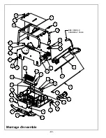
Страница 108: ...22 Montage d ensemble 6 1 66 0 3...

Страница 109: ...COMPLETE 1 1 1 1 18 19479 THROTTLE CABLE 1 1 1 1 19 19535 ROLLCAGE 1 1 1 1 20 19537 ENGINE DECK 1 19538 ENGINE DECK 1 1 20317 ENGINE DECK 1 21 19790 HOSE HYDRAULIC 1 1 1 1 22 F042004FWS FWS 1 4 20 x 1...

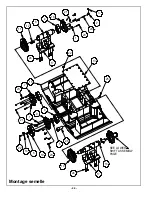
Страница 110: ...24 6 2 5 6 7 66 0 3 Montage semelle...

Страница 111: ...P 1 1 1 15 16331 BASEPLATE MACHINED 1 1 1 16 16599 INPUT SHAFT 1 1 1 17 16608 EXCITER WEIGHT GPR99 4 16260 EXCITER WEIGHT GPR135 4 20312 EXCITER WEIGHT GPR160 4 18 17104 BEARING COVER EXCITER BREATHER...

Страница 112: ...26 Montage arbre inf rieur...

Страница 113: ...IX PIN CARRIER 1 10 16242 SHIFT SHAFT 1 11 16254 DOWEL PIN M10 x 70 1 12 16264 BEARING COVER EXCITER 1 13 16446 FITTING 90DEGREE PARKER 1 14 17023 KIT BLEEDER SCREW 1 15 17275 SHIFT SPOOL 1 16 17276 H...

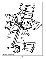
Страница 114: ...28 Handle Assembly...

Страница 115: ...1 17 19422 CONTROL HANDLE 1 18 19442 SHOULDER BOLT 5 16 x 3 4 1 4 20 2 19 19519 HANDLE GRIP 1 00 I D x 4 1 2 FOAM 3 20 19526 SHAFT CONTROL 1 21 19533 SHOCK MOUNT HANDLE 2 22 F023204FSS FLAT SOCKET HEA...

Страница 116: ...30 Boitier de commande...

Страница 117: ...250 FITTING SOCKET HEAD PLUG 1 7 19427 HOUSING CONTROL HEAD 1 8 19430 SHAFT WIPER SEAL 1 9 19431 HYDRAULIC SHAFT SEAL 1 10 19433 BEARING GUIDE RING 1 11 19434 BEARING GUIDE RING 1 12 19527 PISTON SHAF...

Страница 118: ...32 6 0 1 1 21 6 5 48 5 0 6 06 1 21 3 Gasoline Engine Assembly...

Страница 119: ...580 SPACER CLUTCH 1 1 7 16665 WASHER MOUNT 1 1 8 16676 BELT GUARD 1 1 9 16974 HOSE OIL DRAIN 1 1 10 17467 BELT GUARD MOUNT 1 1 11 F052408FSS FSS 5 16 24 x 1 ZP 4 4 12 F061618HCS HCS 3 8 16 x 2 1 4 GR...

Страница 120: ...34 Diesel Engine Assembly...

Страница 121: ...R BATTERY BOX 1 21 19547 MOUNT BATTERY BOX 2 22 19549 BRACKET BATTERY HOLD DOWN 1 23 19551 BATTERY 12 VOLT SIZE U1 300CCA BUY LOCALLY HAZARDOUS TO SHIP 1 24 F042006FWS FWS 1 4 20 x 1 ZP 6 25 F0420ELN...

Страница 122: ...LTS 5 This warranty does not cover the cost of transportation and other expenses which may be connected with warranty service but not specifically mentioned herein 6 This warranty does not cover any u...

Страница 123: ...37 NOTES...

Страница 124: ...38 NOTES...

Отзывы: